Showing posts sorted by date for query Soundcard Interface. Sort by relevance Show all posts

Monday, April 27, 2026

Down Memory Lane: Reboot Amateur Radio WhatsApp Group – Reboot Coffee Drink Event 20 July 2019 9 AM STARS Restaurant, Mossel Bay

The Reboot Amateur Radio WhatsApp Group as well as the Reboot Coffee Drink Event is open to all radio amateurs and prospective radio amateurs in South Africa. All our events are informal and not club related in any way!!


Saturday 20 July 2019 was a cold and wet winters day due to a strong cold front that resulted in gale force winds, rain and snow on the high mountains of the Western Cape. But as they say in the classics the show must go on. Only the “brave” attended the Coffee Drink session in Mossel Bay which was again an enjoyable and successful event despite the low attendance figure.

Those present by way of mind: = 21

Kobus ZS2BBB, Mari ZS1MEH, Hentie ZS1LH, Jacques ZS1WC, Danie ZS1DJB, Dave ZR1OAC, Ettiene ZS008, Christi ZS4CGR, John ZS1ZR, Hennie ZS1IK, Nick ZS1N, Georg ZS1GFL, Chris ZS1M, Casey ZS1AAS, Abe ZS1ZS, Jimmy ZS1RB, Willie ZS2CC, Llewellyn ZS003, Conrad ZS1KG, Andre ZR1E en Johann ZS2BVD.

Those present in the flesh: = 6

Johan ZS2I, Thys ZS1TBP, Francois ZS1Q, Beat ZS1HB, Russel ZS2AHF and Johan ZS1I.

All present were welcomed by the administrator of the Reboot Amateur Radio WhatsApp Group. Once again there was no formalities and the only business of the day was the “Rondomtalie” / “Round Robin”, Mini Lectures/Demonstrations. (Participation is not compulsory! You can just sit and enjoy your coffee and learn.) It is impossible to provide all the finer and juicy details of the event. Moral of the story is to attend each and every coffee drink event.

Rondomtalie/Round Robin:

  • Beat ZS1HB Mossel Bay displayed the DIY 2 Meter J-pole Antenna he constructed. He gave and overview of the working of this large and well built antenna. He indicated that this antenna will be used as a replacement antenna for the 145.600 Mhz Danabay Repeater. The J-pole antenna was constructed from 22mm copper water pipe. The antenna is fitted with a fine tuning bolt to adjust for the lowest SWR. Beat confirmed that the SWR reflected iro the antenna is 1:1 at 145.600 Mhz. The attached photos and documentation were supplied by Beat for distribution to any radio amateur who is interested to build such an antenna. After the J-pole discussion/demonstration Beat gave an update from his previous talk on the AIS (Automatic Information System) for ships and how he monitors VHF propagation all along the southern coast of South Africa. This discussion also included aircraft tracking and aircraft scatter. Thys then explained how APRS is used in 18 wheelers to also monitor VHF propagation. Most interesting!!
  • Russel ZS2AHF George told the participants that he is busy restoring a grand old Kenwood TS520S HF Radio. He is currently experiencing a problem to locate the “paddle” or “bat-handle” switches (Send Receive, Vox, Noise Blanker etc.) for this specific radio. One cannot find new replacements anymore. If anybody can help to relocate a scrapped TS520S or 3D printed “paddle” or “bat handles” Russel will be most grateful. Russel is also busy constructing a LED Stand Alone Frequency Counter for this Kenwood TS520S and will keep us updated on his progress in future. Come on guys let us try to help Russel to get this fine old “lady” radio again in a full operational state!!
  • Johan ZS1I Mossel Bay displayed the Southern Cape 2 Meter Hospital Slim Jim Antenna. He explained where the name for this antenna originated from. This antenna was constructed by Johan ZS1I many years ago when Isak ZS2I (SK) was in the local hospital in Mossel Bay. He had a HT radio in hospital but was not able to get into the 145.600 Danabay Repeater from his hospital bed. This antenna was taken to the hospital on several occasions. Isak was able to communicate with his fellow radio amateurs through the repeater while in hospital. This antenna is still today available on loan to any radio amateur who would like to use it from the local hospital in Mossel Bay. One would find it strange for somebody that was sick in hospital to still speak to his fellow radio amateurs for his hospital bed. Those who knew Isak (SK) would know that nothing was to much for him in life. He lived a full “Amateur Radio” life till the end!
  • Johan ZS2I Mossel Bay (Just for clarity Johan is Isak’s (SK) son and he now hold the call-sign ZS2I) If Johan tells you that the current sun cycle is near the bottom and responsible for poor HF conditions then you must know that he knows what he is talking about. Johan an avid DX Chaser gave an overview of the current HF band conditions and DXpeditions. He however stressed that there is still openings at times and that one must be patient. He encourage all radio amateurs to call CQ on the bands at any time and not just except the fact stated by so many that the bands are “dead”. CQ CQ CQ.....!!!!!!
  • Francois ZS1Q George recently acquired a new 2m HT radio. He wanted to connect this radio to an external antenna but the connector on the radio required a specific adapter which is not locally available in George. This was no problem for Francois and he decided to construct a unique extension cable from parts that he salvaged from other old radios. This extension cable works far better than the advertised connector as it is far more flexible to use and easier to install to the radio. Francois you should patent your extension/adapter cable for future marketing.
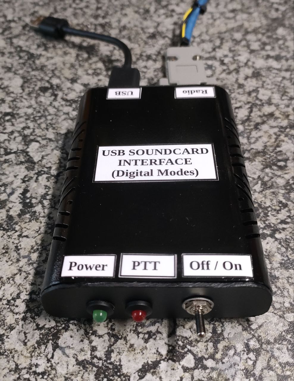
  • Thys ZS1TBP Mossel Bay. We were all glad to see Thys at the session as his work do not always allow for him to attend the coffee drink sessions. Thys displayed and demonstrated the working of a homebrew USB Soundcard Interface that was designed and constructed by Danie ZS1DBJ. (currently visiting Australia). Danie designed the PCB with an on/off switch, RX/ TX volume controls and a PTT force switch. Thys has been using this unit very successfully on his Kenwood TRC80 and it is working flawlessly.

Other matters discussed by the participants:

  • FT8 DX and Normal Modes and Changes.
  • Tracking Aircraft and Flight Radar. (ADB-S)
  • Interference and rising RF noise levels. It is not going to get better just worse!
  • Ship to Shore Beacons. (AIS)
  • APRS and 18 wheel trucks.
  • Sun Cycle and HF Bands.
  • Painted antennas do not work? Is this true?
  • How to make the Hospital Slim Jim directional. Wil cleaning the antenna on the one side make it directional?
  • Static electricity and HF antennas on large 18 wheel trucks.
  • Interference on HF coming from the ABS braking system on large 18 wheel trucks.
  • Lightning, static discharge and amateur radio antennas, earthing/grounding, protection etc.
  • Short amateur radio related story from the past - 2 meter repeater ragchewing in the Southern Cape (1am to 4am in the morning) by those who cannot sleep at night.

A big thank you to all the participants for sharing their knowledge with us all. Highly appreciated!

Finally: A new coffee drink record (2 hours 12 min) was set during the event. Record? NO attendees just enjoyed themselves so much that time was no factor at all.

I concluded the event by thanking everyone for attending the event. Even though the attendance figure stood at 6 it really does not matter and has no effect on those present. The topics discussed reflected this fact. A great time was enjoyed by everyone!

We look forward to the next Reboot Coffee event which will be held in George on the 17 August 2019 at 9 am. The venue in George will be announced closer to the date.

73

Johan ZS1I
Mossel Bay
21 July 2019


Photos:

J- Pole Construction info - ZS1HB
 J-Pole Radiation pattern - ZS1HB
 J-Pole Plan - ZS1HB
DIY Extension Cable - ZS1Q


 Thys ZS1TBP admiring the work of Danie ZS1DBJ
 USB Sound Card Interface - ZS1DBJ
 The large J-Pole constructed by Beat ZS1HB
 Close up USB Sound Card Interface displayed by Thys ZS1TBP
 Beat ZS1HB with the 22mm copper J-Pole antenna
 The 6 BRAVE men enjoying themselves!!

 The Southern Cape 2m Hospital Slim Jim - ZS1I
 Bottom section of the Southern Cape 2m Hospital Slim Jim
 Snow on the mountains
 Cold cold cold!!
Snow on the mountains - ZS1Q

Saturday, November 22, 2025

Building Low Budget Antennas - DIY Magnetic Loop Antenna for 20 (14Mhz) - 6 (50 Mhz) Meters (Part 1)


I continue with the series of low budget antenna "builds".   In the series I will be looking into building antennas that is:

  • Highly Portable
  • Cheap to Build
  • Easy to build (Novice and Experienced builders)
  • Use readily available material from the local hardware store
  • Needs minimal tools to construct
  • Needs only a SWR Meter to do some final tuning and adjustments.  However if you do have an antenna analyzer, that will be a bonus.
  • Highly affective with possible gain.
  • Light weight and easy to install or to dismantle
  • Fun to build and play around with.            

Please note that none of the antennas that I will be constructing is my personal designs.  Credit will be given and links provided where you can find more information about the antennas.

I trust that new, novice and experienced radio amateurs that will be building some of these antennas  will find them of great use and enjoyment.  Isn't this what amateur radio is all about?

Now lets look at a short explanation of  "What is a small transmitting magnetic loop antenna?"

A small transmitting magnetic loop antenna is a compact, resonating antenna made of a conductive loop with a high-voltage capacitor. It is designed for use in situations with limited space, such as in amateur radio, and can provide good performance when carefully constructed to minimize losses. The antenna operates by using the magnetic fields of radio waves and has a unique, doughnut-shaped radiation pattern with nulls at right angles to the loop's plane. 

How it works
  • Loop as an inductor: The main loop acts as a large inductor in a tuned circuit.
  • Capacitor for resonance: A variable capacitor is placed in the loop's break to form an LC circuit that resonates at a specific frequency.
  • High-Q circuit: This high-Q parallel-tuned circuit results in a narrow bandwidth but high efficiency, making it excellent for receiving weak signals and transmitting.
  • Coupling loop: A smaller, secondary loop (the "feed loop" or "coupling loop") is placed near the main loop to transfer the radio frequency energy from the transceiver to the antenna.
Characteristics
  • Small size: Its circumference is typically less than one wavelength, making it ideal for portable use or areas with antenna restrictions.
  • Directional pattern: It has a doughnut-shaped radiation pattern, with the signal being strongest in the plane of the loop and weakest at the points perpendicular to it.
  • High efficiency: Despite being small, its design can achieve high performance, especially in the HF bands, with careful construction that minimizes resistive losses.
  • High voltage: The voltages across the tuning capacitor can be very high, so it's important to use high-quality components and to be careful not to touch the antenna while transmitting.
Common uses
  • Amateur Radio: Its compact size makes it popular for portable operations, like Field Day, and for home use where outdoor antennas are not permitted.
  • Military applications: Its small size and high performance make it suitable for military use.

In any project one needs a plan, diagram, guidelines and information.  At least that is my way of constructing any DIY Project.  I research the project thoroughly before I start any work.  I did exactly this before I started on this project.

Now the Internet is your friend but can also by your enemy if you just jump in and start constructing the first plan you find.  I was looking for the dimensions of  DIY Magnetic Loop Antennas and ran into a Small Transmitting Loop Antenna Calculator at 66pacific.com

Small transmitting loop antennas, commonly called "magnetic loops" or "mag loops," can give surprisingly good performance when they are carefully designed and constructed. Although this online calculator is intended to assist with designing and building homemade, ham radio loop antennas for use in the HF bands, magnetic antennas have been constructed that function in the VHF or even the UHF frequencies. This calculator enables you to test the design of an octagonal loop antenna and to answer "what if" questions until you arrive at a design that meets your needs without a lot of experience in electronics.

The small transmitting loop antenna calculator was fed with the following data:

Length of Conductor (Antenna "Circumference")  =  1.360 meters

Diameter of Conductor = 2.5 centimeters

Frequency = 50.2

Transmitter Power = 5 Watts

After calculating the following information were provided:

Antenna efficiency: 94% (-0.3 dB below 100%)
Antenna bandwidth: 209 kHz
Tuning Capacitance: 13 pF

Capacitor voltage: 545 volts RMS
Resonant circulating current: 2.20 A
Radiation resistance: 0.484 ohms
Loss Resistance: 0.032 ohms
Inductance: 0.785 microhenrys
Inductive Reactance: 248 ohms
Quality Factor (Q): 240
Distributed capacity: 4 pF

Antenna "circumference": 1.360 meters

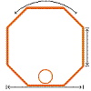
Loop antenna Side length: 0.170 meters
Antenna diameter: 0.4 meters

Comments:
The specified conductor length of 1.360 meters is OK.

Conductor length should be between 0.725 and 1.45 meters at the specified frequency of 50.2 MHz.

For highest efficiency, the conductor length for a small transmitting loop antenna should be greater than 1/8 wavelength (greater than about 0.725 meters at the specified frequency of 50.2 MHz).

To avoid self-resonance, the conductor length for a small transmitting loop antenna should be less than 1/4 wavelength (less than about 1.45 meters at the specified frequency of 50.2 MHz).


Input Values:
Length of conductor: 1.360 meters
Diameter of conductor: 2.5 centimeters
Frequency: 50.2 MHz
Transmitter power: 5 watts

The transmitting loop I decided to construct was inspired by Peter VK3YE and he calls the antenna, "The SummerLoop II" a pedestrian mobile magnetic loop for 20 to 6 Meters. Here are the links to some of his videos where he explains and demonstrates the antenna.

The SummerLoop II 14 - 50 MHz pedestrian mobile magnetic loop 

Tiny loop works 'Magic Band' DX on 50 MHz

With all the information now on paper I was ready to move onto the next phase and that was to gather all the materials I was going to need.

Materials that I used:

1 x 25mm x 3mm x 3m  Aluminium Flat Bar
1 x 25 - 50 pF Beehive Trimmer Capacitor
1 x 25mm x 80mm x 2mm Single Side PCB (Must be single sided to lessen capacitance)
1 x 16 mm x 1820mm Wooden Dowel 
2 x 80mm x 80mm x 4mm Plastic Cutting Board 
1 x SO239 Connector (Optional)
1 x Electrical Eye Lug (Terminal)
1 x 205mm x 2mm Brazing Rod or Stiff Copper Wire
2 x 35mm x 4mm Stainless Steel Bolts + Washer + Lock Nut and Wing Nuts
1 x 12mm x 4mm Stainless Steel Bolts and Lock Nut
2 x 15mm x 3mm Stainless Steel Bolts and Lock Nuts

Odds and Sods:

Cable Ties
Hot Glue Sticks
Self Amalgamating Tape
Solder
Solder Paste
Coax Cable (RG58CU Mil Spec) 50 ohm
Marine Silicone Sealant
 
Tools:
 
Metal Punch
Drill
Drill Bits 4mm + 3mm
Hack Saw 
Hot Glue Gun
Soldering Iron
Screw Driver (Small flat)
DIY 135 Degrees Bender to form Hexagon (See image and description)
 
Test Equipment:
 
SWR Meter
Antenna Analyzer (If you have one but not compulsory)
Amateur Radio Tranceiver
Coax Patch Leads
Mast (Non conductive)
Coax feed line cable  5 m  RG58CU 50 ohm
Power Supply for Radio 
Soundcard Interface
WSJT-X Software
 

Building the Antenna:

I am not going to go into detail how I constructed my version of the antenna. I will however describe my findings in constructing and testing the antenna.  The images below provide good detail of how I constructed the loop.


Image:  Peter VK3YE  (Click on image for larger view.)

More information on the build and use of the antenna available at:

 
Website Peter VK3YE (Click to view website) 

My build observations and findings:
 
Now how did I bent the hexagon figure of the antenna?  I decided to construct a jig to assist me to bend the 135 Degrees needed to turn the aluminium flat bar into a hexagon configuration aka Loop Antenna.

I uses stainless steel bar and scrap that I had lying around in the workshop.   See images below.


Now the bending process is quite simple as illustrated in the images below.


The measurement at the open end of the loop is 85mm - 85mm = 170mm.  To provide space for the capacitor and PCB cut 10mm of each side making each side 75mm.  The PCB with the capacitor will now fit comfortable in the cut out space.  See images below:


I used a 25 pF Beehive Capacitor as this is all that I had on hand. According to the calculator I only need 13 pF for 6m operation.  The 25 pF also allow for 10 and 11 meter operating. 

The  Beehive trimmer is mounted on a 25mm x 80mm x 2mm piece of single side fiberglass printed circuit board. This must be single sided copper to lessen capacitance. I used a hacksaw to separate the copper into two large pads, each connected to a terminal of the capacitor.

Screws hold as much of each pad as possible against each end of the flat aluminium loop. Sand the facing surfaces to lessen resistance. If the loop is to be used permanently outside as a courtyard or balcony antenna, consider the risk of reaction between dissimilar metals and waterproof accordingly.  I intend to change the above arrangement.  An update will follow in this regard.

I used 2 x 35mm x 4mm Stainless Steel Bolts + Washer + Lock Nut and Wing Nuts to hold the loop ends to the circuit board. Install so their heads are pointing down. They should be long enough for there to be about 20mm thread protruding from the nut. The reason for this is mentioned later.

2 x 80mm x 80mm x 4mm Plastic Cutting Kitchen Board material adds rigidity to the top and bottom of the loop and lessens stress on the circuit board. Two 16mm holes allow a snug fit with the 16mm vertical dowel that comprises the antenna's handle.

An insulated knob on the capacitor lessens hand-capacitance and makes adjustment easier. I used an old fibre pen casing as an isolation knob. The one end happened to fit snugly onto the rotating section of the trimmer capacitor.

Feed Arrangement:


Image:  Test feed arrangement

My feed arrangement measurements differ from that of VK3YE.  I also used the gamma-style feed. I tried the measurements of VK3YE but the SWR was above what I wanted. I decided to extend the feed by another 40mm of copper wire.  The SWR came down but was still not ideal. I added another 70mm and played around with the position.  Well this extension lowered the SWR to 1.15 on 28.1200 Mhz to 1.53 on 50.2400 Mhz.  Good enough for me.  I then constructed the final gamma-style feed using brass brazing rod.  The brass rod is very sturdy and works fine.


Now what about the other bands?  20m, 17m, 15m and 12m.  For the project that I intend to use the loop with, I currently do not need the other bands.  However others might need more bands.  Firstly you will need to add more capacitance.  This is achieved by adding a fixed capacitance across the trimmer. Peter used a 68pF polystyrene capacitor that serendipitously allowed coverage of 14 MHz with the trimmer nearly meshed and 18 MHz with it nearly open.

A 630 volt capacitor is adequate for five watts. If you only have lower voltage rated capacitors, then two or more wired in series relieves voltage across each one. 120 and 150 pF in series will provide close to the required 68 pF.

Though desirable for low resistance, a soldered connection is impractical as the capacitor must be removed for higher band coverage. Peter mounted it on a piece of chopping board. It has two banana sockets which mate with the 4mm bolts that hold the beehive trimmer.   See images by clicking on the link above.

I have a 470pf  750 volt fixed capacitor but as yet have not tried it.  I will use a wing-nut arrangement to fix this cap to the beehive capacitor.  An update will follow in this regard.

I am quite happy how this antenna turned out but as they say the proof is in the pudding.  I will later provide a performance update but for the time being I would like to share my findings up to now:

  • I enjoyed building this antenna and would like to thank  Peter VK3YE for making the information available about this antenna.
  • This antenna is very sensitive to tune and also has a very narrow bandwidth.  Loop antennas is highly dependent on being precisely tuned to a specific resonant frequency. For small loop antennas, their size is often less than half a wavelength, making them inherently narrow-band and requiring constant re-tuning if the frequency changes. This characteristic, however, makes them highly selective and good at rejecting unwanted signals and noise, which can be an advantage in certain applications like receiving in crowded radio environments.
  • I found that the capacitor and feed arrangement work in "tandem" and in my case I used a 25pf capacitor and had to lengthen the gamma-feed as a result.
  • In my humble opinion the antenna I constructed lends it very well to pedestrian mobile operations.  If you live close to sea level then special precautions need to be taken to prevent corrosion even while pedestrian mobile.  Seal areas between the aluminium and PCB with marine silicone to prevent moisture getting in between the two metals. If not sealed properly the performance of this antenna will deteriorate with time.

Preliminary Test Results:

I really did not go into a full out testing and using this antenna.  The only testing I have been doing is with the Nano VNA and a test or two on air RX and TX "excursions" in my shack between four walls and two windows with metal burglar bars.  Surely not the way to test this antenna but in Part 2 I will describe a full "work out" for this antenna.  Images below depict the "Faraday Cage" operations.

Herewith more images regarding the antenna  (Click on images for larger view.)


Part 2 to follow soon

Tuesday, June 17, 2025

Let's build a KISS USB Soundcard Interface for Digital Modes (Part 1)


Through the years I have build many types of Soundcard Interfaces.  Some KISS models and others with micro controllers.  You can find some of the interfaces HERE. They all enabled me and many others to work various digital modes.  Nowadays many of the new radios do not need the conventional soundcard interface to allow you to work digital modes.  Several years ago I found The USBLink design by Julian Moss G4ILO  now SK.  I kept a copy of his article on my Soundcard Interface file for many years long before Julian went silent key.  About two weeks ago I paged through my file and found the article.  Now I do have several types of Soundcard Interfaces in my shack but this interface article gave me an idea that I will discuss in Part 2.  First off I need to build the USBLink Interface and test it live on the air.   The article of the USBLink is available HERE.  

This interface is in my opinion a KISS unit with no bells and whistles.  Herewith a few features that makes the unit a KISS interface:

1.  No Serial to USB interface / cable needed to handle PTT.

2.  No 1 : 1 (600 ohm) isolation transformers needed.

3.  Relatively low cost to construct the unit.

4.  Relatively small size compared to other homebrew interfaces. (Ideal for portable operation.)

5.  Does not use opto-isolation of the PTT line. (Not needed)

6.  Inexpensive USB Sound Card can be used. (Chinese cheapies will also work but I would rather buy a better quality product.)

7.  Project can be constructed on a piece of veroboard.

8.  No dedicated power supply needed for the Soundcard Interface.

9.  Diodes added for PTT transistor and radio protection. (I would however add another switch to cut off the PTT line going to the transceiver to prevent accidental PTT activation when unit is left unattended.)

10.  Plug and Play Unit - No drivers to install.

Finally:  This is a simple low cost circuit which works well and allows you to operate sound card digital modes without tying up your computer's built-in sound card.  I constructed this interface and tested the interface on VHF.  In part 2 I will provide feedback on how the interface behave on HF but from what I observed using a VHF transceiver it should work just as well on HF.  Although I am not in favor of using VOX in any way in amateur radio, I do not foresee any issues using this interface attended.  I would not leave this interface unattended and therefor suggested the additional switch  between ground and PTT to prevent accidental transmissions.

Images:  (Click on images for larger view.)


Closure of this ZS Link Network Blog - 29 April 2026

This will be the final posting on the ZS Link Network Blog. This blog will no longer be updated but will remain available for research an...