Tuesday, March 19, 2024

Upgrading of the 145.750 Mhz Aasvoelkop Repeater Site in the Southern Cape Area (Part 2)


Image:  The new 145.750 Mhz Tower and Repeater  (Click on image for larger view.)


It is done and dusted .......is it really? 

In Part 1 available HERE the upgrading of the 145.750 Mhz Aasvoelkop Repeater Site started in all earnest with the casting of the concrete block for the 20m tower that would be installed once the block has harden and cured for a period of at least 28 days.  In Part 2 you will be able to view the full upgrade taking place, the tower installation  and the repeater put back into service.

The upgrade of the 145.750 Mhz Aasvoelkop Repeater Site in the Southern Cape Area was undertaken this past Sunday, 17 March 2024.  12 people were on site which included radio amateurs and non radio amateurs.  The scheduled starting time to commence working was duly set and the team started working on site at around 07h00.  All the necessary equipment and new tower parts were carted up to the site using 4 x 4 vehicles.  Take note that the last 15 meters of the mountain peak was only accessible by climbing and carrying equipment by hand to the final site.  The tower sections alone  constituted 20 meters when erected.  As can be seen from the images erecting the new tower was no easy feat and specialized gin-pole and winch was used to pull the tower upright.  Well this could only happen after all the old equipment and old tower with antennas were taken down.  In my opinion this upgrading is a two day task but the team proved me wrong.  

The new tower and equipment had to be carried up the mountain top, installed and then the old tower and equipment had to be carried down the the mountain top.  Very hard work and intensive labor but before the work started the men formed a circle and ask the Almighty to protect and bless the work being undertaken.  It is easy to get hurt especially if so many tasks are to be performed and with 12 people onsite everyone must clearly know what is expected of him and the team.  It took the team most of the day to upgrade the repeater site.  Conditions were also not all that favorable.  The sun literally hammered open skin areas and the wind was of real concern as a South Easterly was getting stronger as the day progressed.  Thankfully in the end the team was able to lift the 20 meter large tower up into its place to great relief of all those in attendance.  (See video)

Once the tower was secured it was time to setup the repeater box and all the equipment.  This also took some time but soon it was time to switch the repeater back on.  This must have been the highlight of the day to stand back and see the new tower and installation in its full glory.  Well it was getting late in the afternoon and it was time to cleanup the site and only leave a footprint in the soft gravel here and there. Everybody returned safely to their respective QTH's, tired but completely satisfied with a task well done!  Neither did some know how their body will feel the next morning when they had to get ready for a full days work.  Sore and rather tired but South Africans do not let a few pains and aches get them under.

Here is a short list of some specifications of the Repeater on site:

Antenna:  Diamond X510  (Two Stacked Dipoles were installed on the tower as backup antennas.)

Band:  2m and 70 cm

Gain:  8.3 dB on 2m and 11.7 dB on 70 cm

Watts:  330 w on 2m and 250 on 70 cm 

Maximum Wind Resistance:  90 Mph

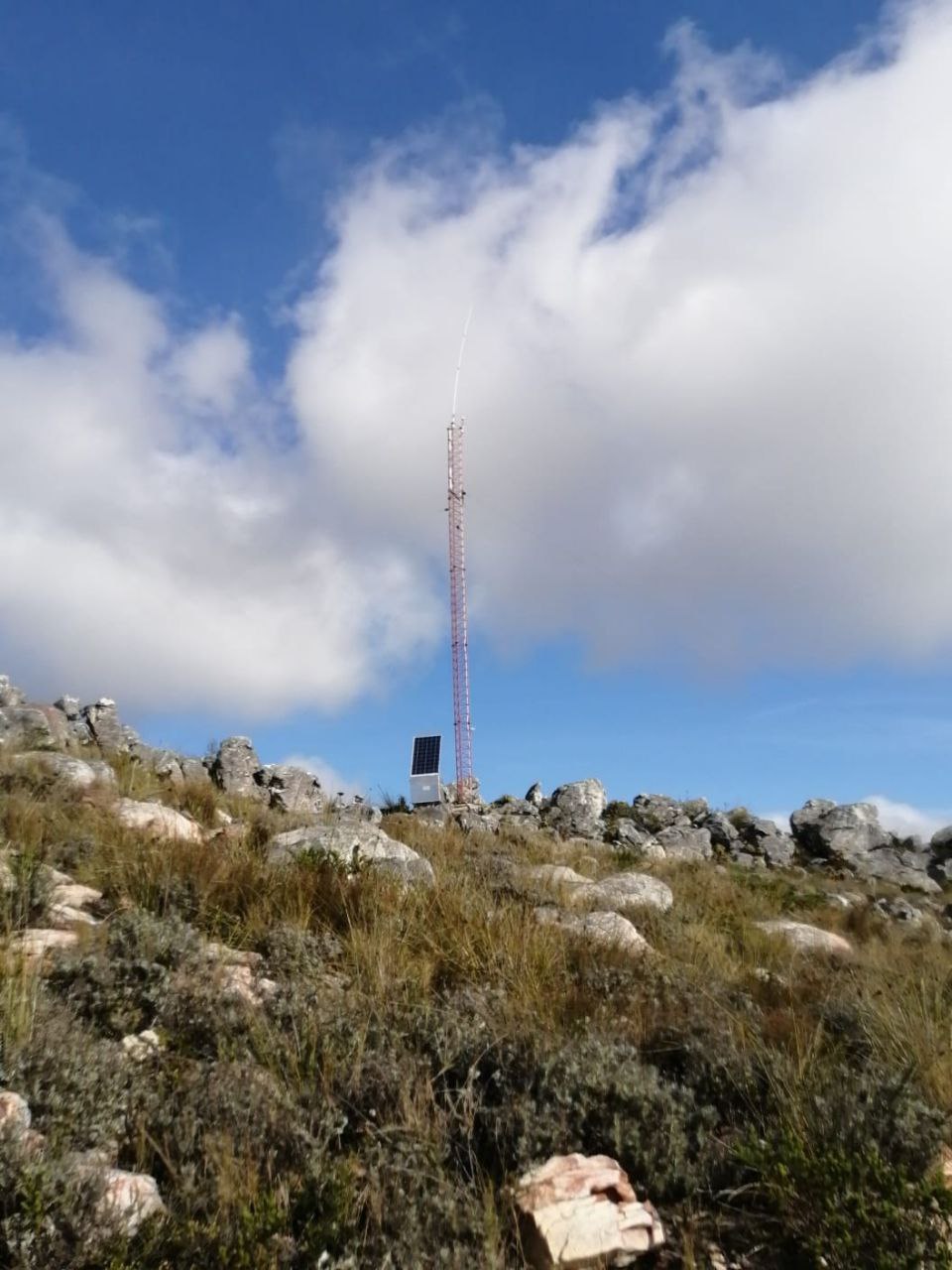
Height of Tower:  20 Meters

6 x Cavity Filters

Backup Battery

Solar Panel

Odds and Sods

Reception Reports:  (To be discussed in Part 3 in a future posting.)

I am not going to go into full detail here as reception reports is still received on a daily basis.  Wow .... Phenomenal is the way to describe the reception and transmission of this repeater after the upgrade.  This repeater is in my opinion now the No 1 repeater in the Western Cape if not the whole of South Africa.  I have been in this "game" for more than 30 years now an I can clearly vouch that this is the best repeater I ever worked.  I will in Part 3 give a full overview of the reception and transmission of this repeater after I received all the outstanding reports.  Up to now I am convinced that this  145.750 Mhz Aasvoelkop Repeater is going to reveal a few surprises in future.  Mark my words!!

Finally:  A big word of thanks firstly to Johann ZS1AAC for the vision and outlook to put up a repeater for all radio amateurs to use irrespective if you belong to any club or organization.  Johann proudly indicated that this tower and repeater was erected for future generations in amateur radio which include all radio amateurs but also the young "Hammies". What a vision and gesture for the future of Amateur Radio.  Johann we salute you!!

Now this would not have been a one man venture.  To all the other radio amateurs and non radio amateurs (Unfortunately I do not have all the names) who assisted in making this repeater a reality and also for all the hard work that they put in,  a big thank you!  You did not only do it for yourself and other radio amateurs but for the continued existence of Amateur Radio in South Africa.  What stands out is the fact that radio amateurs and non radio amateurs worked in tandem to make this dream of Johann ZS1AAC come true.  The way and spirit in how this was done is clearly an example to all of us.  Then there are many radio amateurs that are not able to assist in this project by means of hard labor on the mountain site but contributed by means of donating equipment and  money. We all know that the installation and upkeep of repeaters are costing money.  Others again contributed by way of moral support, reception reports, ham spirit etc.  Johann would like to thank everyone who contributed in any way possible to the future of Amateur Radio in the Southern Cape.

This is only the beginning.  I received a heads up from Johann ZS1AAC about future upgrades and installations in the Southern Cape.  Watch this space!!

A special word of thanks must go to Henk ZS1AAD who was the photographer for the day and Thys ZS1TBP for forwarding the images via Telegram to me.  Without the images and the videos this post would not have been possible.  Dankie, Henk en Thys! 

Images:  Click on images for larger view.


Image:  Johann ZS1AAC in deep thoughts on the big task ahead.


Top image:  THE TEAM!!  (Click on images for larger view.)

Starting from the back row on the left side:

Mario ZS1MV, Henk ZS1AAD, Johann ZS1AAC, Eben ZS1EP, Johannes ZS1XR and Bruce (non radio amateur)

Starting from the front row on the left side:

Abrie (non radio amateur), Attie (non radio amateur), David (non radio amateur) and Henry ZS1SB

Inserted photo:  Dolf ZS1DRP (Dolf took the above photo.  The editor of this article inserted the photo of Dolf.  Now you have a photo of THE TEAM that worked on the repeater site.)


Image:  Some of the "manne" enjoying the "Vetkoek" made by Nicolene ZS1HAR before the hard work starts.

Image:  Planning session before work commences

Image:  Equipment that needed to be carried to the top of the mountain

Image:  Old tower and Repeater Cabinet

Image:  Putting base plate in position

Top 4 images:  Base plate work


Images above:  Tower work in progress


Above:  New tower lifted and in the air.


Above images:  Old and New Tower

Above image:  The view from Aasvoelkop is spectacular

Below:  Videos of the upgrading of the 145.750 Mhz Aasvoelkop Repeater in the Southern Cape 


Monday, March 18, 2024

Rattlegram Tests Southern Cape, Free State. Eastern Cape, Western Cape, Northern Cape and Gauteng.

In a previous post available HERE I wrote an article about Rattlegram and Ribbit. In the previous article you will find a wide variety of information pertaining to Rattlegram and Ribbit which I am not going to repeat in this article.

An audio file was created where Rattlegram and Ribbit was explained in ZS1I Ramblings.  The file can be downloaded at: 

Audio File Download: ZS1I Ramblings 31 August 2023 Issue 8 - Meet Rattlegram and Ribbit!

During a conversation on Telegram I mentioned that I would like to test Rattlegram via several "modes" methods of communication.  Myself and Christi ZS4CGR decided that we will have a "informal" test session this past Saturday evening.  We did a few tests which was unfortunately not successful possibly due to the current Internet issues.  Now some of the purist might say that this is not the way to test an emergency communications program via the Internet.  Let me say that you use anything that is available when there is a emergency or a disaster. End of debate!  We decided that we will carry on testing Rattlegram and that the next session would be held after the Bo Karoo Amateur Radio Club Bulletin this past Sunday the 17 March 2024.  No announcement of any kind was made from my side but what a surprise when the following radio amateurs joined the test session:

1.  Christi ZS4CGR   Luckhoff

2.  Gerrit ZS1KLO   Rheebok, Mossel Bay

3.  Thys ZS1TBP   Port Elizabeth

4.  Curtis ZS6CMO  Alberton

5.  Johan ZS1I  Mossel Bay 

6.  Zayn ZR3VO   Orania

7.  Fred ZS5SAM (Div 1)  Barrydale  (Did not join the session but decoded some of the messages via AllStar and informed us of his incognito presence during the test session.)

I am not going to go into great detail here as it will take to long.  If you would like to find out more then join us  for the next round of tests that will hopefully take place this coming Sunday afternoon at around 15h30 SAST.

We did the following tests:  (Result in Green)

1.  Cellphone to Cellphone  PASSED

2.  Cellphone to VHF Radio  = VHF Radio to Cellphone  PASSED

3.  Cellphone to VHF Radio to Repeater = Repeater to VHF Radio to Cellphone  PASSED

4.  Cellphone to VHF Radio to Echolink = Echolink to VHF Radio to Cellphone  FAILED

5.  Cellphone to VHF Radio to AllStar = AllStar to VHF Radio to Cellphone  PASSED

6.  Cellphone to DroidStar to DMR = DMR to Droidstar to Cellphone  FAILED

Next test to undertake:  Cellphone to HF Radio = HF Radio to Cellphone  NOT YET TESTED

We will once again test those "methods" that failed in future.

Please note the Cellphone running Rattlegram is only used as a "computer" and need not be connected to a cellphone tower or the Internet.

Finally:  I would like to thank everybody that participated in the Rattlegram Tests and invite other interested radio amateurs to join the next test session.

Herewith a few screen-print images of the tests conducted.  (Click on images for larger view.)


Friday, March 15, 2024

Obtaining COS from a USB External Stereo Sound Adapter for Echolink or AllStar


There are numerous USB Soundcard Adapter (FOB) modification methods shown on various web pages on the Internet for AllStar. My goal here was to make it as simple (KISS) as possible. There are two tricky connections for COS and PTT if you want to solder wires to the 48 Pin IC. (CM108 or CM119) Now for us older radio amateurs whose sight is impaired and even with magnification it is quite difficult to work on surface mount components if you do not have the correct tools. In the previous AllStar build I destroyed two CM108 units due to bad eyesight.  Having build a Radioless AllStar Node I found a way around having to solder any wire to the 48 pin Sound IC for COS.  I do not need PTT (Pin 13) as this unit uses a microphone to do the PTT.

I used the above 7 in 1 USB Soundcard Adapter.  Please ensure you buy the good quality adapter and not the cheap imitation/clone adapter from China.  My unit has decent push buttons (as can be seen in the photos below) and a color indication for MIC (yellow) and SPKR (green) where the clone is just black and has “metal spring buttons”.  You can clearly see the different units in the photos below.

Now open the plastic casing by prying it open. Remove the board from the case.  The case and plastic buttons can be discarded. It is nothing more than plastic and does not serve as any shielding. The case has to be removed anyway to allow soldering wires to the MIC and SPKR sockets.  No I never remove the sockets, I just solder the wires to the top of the sockets. Once the PCB has been removed we will only de-solder the bottom (volume down) switch from the PCB.  See photos below.  Once carefully removed you will observe the 4 soldering points for the switch. With the USB plug pointing away from you and the MIC and SPKR inputs (openings) toward you we will solder the COS wire to the top right point of the 4 soldering point where the switch was mounted.   Now how do I know that this is the COS point?  I was lucky enough that the black epoxy blob of my unit was not covering all of pin 48.  Using my multi-meter I tested several areas and found the correct point for the COS.  Once this was discovered it was plain sailing and easy to solder a wire to the point for COS.  I would suggest that you solder a BAT43 diode (covered with heat-shrinking tubing) inline to protect the 48 Pin IC from possible stray voltages, shorts etc.

I fired up the Radioless AllStar Node.  The node worked as it should.  

What is the big deal here?  Well firstly the  CM108 and CM119 generic units must be imported from overseas at an absorbent price.  You have no guarantee that you will ever receive the parcel via SA Postal Services and if you do it can take two to three months to be delivered.  The unit I modified is locally available at R89 a piece.  Please note this will not work if you want to build a General AllStar Node that needs a connection to Pin13 of the 48 Pin IC for PTT.  The "black epoxy" over the IC prohibits any soldering directly to the IC.  However for a Radioless AllStar Node you now have a cheap solution that functions very well.  

Finally:  I really hope that several Radioless AllStar Nodes will see the light in South Africa using this cheap and easy modification.  I will in a future topic post my version of the Radioless AllStar Node.   If you do build a Radioless AllStar Node using this sound card adapter send me your photos of the build to be published on this Blog.  Email:  Click HERE

Images:  (Click on images for large view.)


Cheap USB Soundcard Clone images below.  I have not tested this unit to see if it will work!!


New Amateur Radio Repeater Technology in the Southern Cape

New amateur radio repeater technology soon available in the Southern Cape on the "AasvoĆ«lkop" Repeater Site.  There is great excit...