Showing posts with label Power Outage. Show all posts

Thursday, February 27, 2025

Eskom Loadshedding Solutions - Raspberry Pi Router/Modem "Watchdog" Project: Testing Internet Connection (Part 3)


 Image:  ZS1I AllStar Hub, 145.550 Echolink Simplex Link and ZS-Link SVXLink Reflector

With the recent loadshedding experienced I decided to consolidate several projects that were left hanging due to other more urgent projects or the fact that loadshedding was suspended and there was not really a need to finish such projects.  Well this time around I decided to make a list of unfinished projects and whether loadshedding is suspended early, these projects must be finalized irrespective if there are other more urgent projects.  One such project is the Raspberry Pi Router/Modem "Watchdog" Project.  I received requests from fellow radio amateurs to provide more information setting up the "Watchdog" and what was the end result in connecting it to an AllStar node and LTE Modem/Router. Part 1 and Part 2 is available by clicking on the specific part.

What is the project all about?  In short I needed an automated “watchdog”  to tell me if the Internet was up  or down and if  down to automatically connect to the Internet once it is back up and running again especially during and after loadshedding. (power outages)  If it is up then there is no further action to be taken. In Part 3 I will be looking at a few Linux and Setup commands for this project.  Once you finished constructing the "Watchdog" it is time to "wake it up" and getting it to watch the Internet for connection outages or confirm that it is up and running.

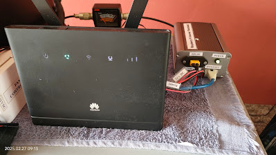
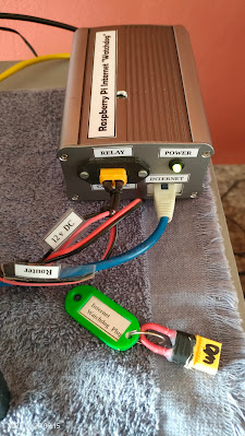
Let's first look at our connections that must be made for the "Watchdog" to work correctly.  

Cables needed:

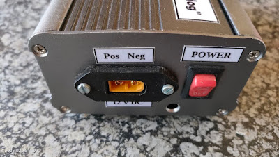
1.  12 v DC Cable to power the "Watchdog"

2.  Ethernet Cable coming from the Router/Modem that you will be monitoring.

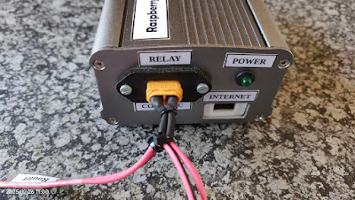
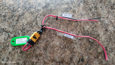
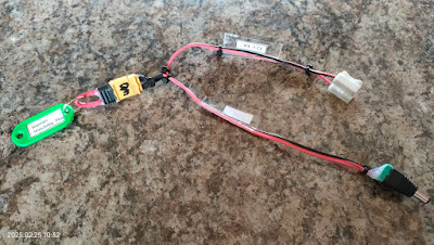
3.  Relay Control Cable.  One end of the cable connects to the Router.  The other end connects to 12v DC going to the Router and the third connection is to the "Watchdog" relay connection which is  Com - NC wired.

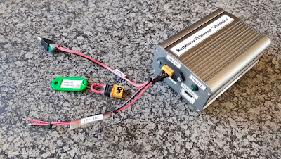
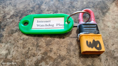
4.  Internet "Watchdog" Bridge Plug -  This is needed when the "Watchdog" is not connected to the Router/Modem.  It is just a wire bridge to give  12 v DC connectivity.

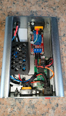
See images for clarity in this regard.

Once you have connected all the cables it is time to switch the unit on.  Wait a few minutes and then retrieve the IP address by either looking in the router/modem or by using software to retrieve the IP address. 

I use VNC to get access to the Raspberry Pi.  Enter  the IP address in VNC as well as your username and password which you must have created when installing the OS.  Once you have logged into the Raspberry Pi you must install Python 3.11.1 if not already installed.  If not installed do a Google search on how to install Python on a Raspberry Pi.  We need Python 3 to run the Internet Watchdog program.  Once Python is installed and you rebooted we need to update the Raspberry Pi.   Open a Terminal window in the Raspberry Pi.

Enter:

$ sudo apt update (enter)

When all the updates are downloaded and installed use clear and enter to clean the terminal window.

We will now write the two script files as shown in Part 2.   Keep Part 2 open in another tab of your browser as we will copy the contents of the two script files into two separate files.  To create each file you will have to follow the procedure listed underneath.

$ sudo su (enter)

$ cd /home/pi (enter)

To create and write a new Python script with Nano:

In the terminal window use:

$ nano filename.py  In our case replace filename with relay_test.py

Copy and paste the relay_test.py in the second browser to relay_test.py  Once copied
press CTRL+S to save the file.
press CTRL+X to exit Nano and come back to the terminal.
Your relay_test.py script file is now created.  Do the same with the relay_final.py script file.  Also open  relay_final.txt and relay_test.txt files by using the above nano method.  Do not copy and paste anything in the relay_final.txt or relay_test.txt files.  Just save them without anything in it.
 
The four files you created will be listed in the /home/pi directory.
You should still be in root@raspberrypi:/home/pi#

Use ls command to list the files.  The files will be listed as:

relay_test.py 
relay_final.py
relay_final.txt
relay_test.txt

Now go to the Applications Menu of the Raspberry Pi (far left top of the screen)
Look for Thonny Python under programming.
Open Thonny
The Thonny Python Program will open 
Click File - Open - select relay_test.py
Click OK
relay_test.py script file will open in Thonny Python
Again click file
Select Open
Click on relay_final.py
Click OK
relay_final.py script file will open in Thonny Python

Time to test if the Internet is UP or DOWN using relay_test.py script

In the Thonny Python Program select relay_test.py  The script has a false IP address to simulate that the Internet is down.

Go to the green round icon with the black triangle pointing  to the right
Click on the icon to run the relay_test.py script
Output will be displayed in Shell (Bottom of Thonny)
 
Output:
 
Date and Time is: 2025-02-24  15:44:12.382124
Testing Internet connection using Ping
PING 1.51.17.1 56(84) bytes of data
(Note the 1.51.17.1 is a fake IP address) to simulate  that the Internet is down)
--- 1.51.17.1 ping statistics ---
5 Packets transmitted, 0 received, 100% packet loss, time 135 ms

1.51.17.1 Internet connection failure
Turning off power to router
Waiting 1 minute to turn router back on
Power up and Reboot router
Nearly there - wait another while!  (Till  >>> appear)

It is clear from the above that we do not have a working Internet connection.  Internet is down!
 
You can replace the IP address in the above script with 8.8.8.8 and again test if the Internet is UP or DOWN.  The output would reflect that the Internet is UP.  No need to change the IP.  We will use the final script to get the "Watchdog" up and running.
 
Next we will use relay_final.py script to find out if the Internet is UP or Down. 

In the Thonny Python Program select relay_final.py 

Go to the green round icon with the black triangle pointing  to the right
Click on the icon to run the relay_final.py script
Output will be displayed in Shell (Bottom of Thonny)
 
Output:
 
Date and Time is 2025-02-24  15:59:35.420916
Testing Internet Connection using Ping
Ping 1.1.1.1 (1.1.1.1) 56 (84) bytes of data
64 bytes from 1.1.1.1; icmp_seq=1 ttl=57 time=66.0ms
64 bytes from 1.1.1.1; icmp_seq=2 ttl=57 time=48.6ms
64 bytes from 1.1.1.1; icmp_seq=3 ttl=57 time=47.4ms
64 bytes from 1.1.1.1; icmp_seq=4 ttl=57 time=48.5ms
64 bytes from 1.1.1.1; icmp_seq=5 ttl=57 time=45.8ms
 
---1.1.1.1 ping statistics ---
5 packets transmitted, 5 received, 0% packet loss, 12 ms
rtt vnin/avg/mox/mdev=45.826/51.277/66.032/7, 446 ms
 
1.1.1.1  Internet connection success.  No further input needed.
 
If the Internet was down the output would be similar to the output we received in relay_test.py simulation.
 
I drilled an inspection hole on the top of the cabinet to view the two LED's on the relay module.  Under normal operation there is a green led that indicates that there is power to the relay module.  There is another relay that will indicate whether the Internet is up or down. (See videos in Part 1)

If only the green power led on the relay module is on then the Internet is up and running.
If the green power led and a red led is lit on the relay module then the Internet is down.

You can now easily see if there is any issues by just looking through the inspection hole.

Finally:  We now need to setup the crontab -e file to run the final script every 10 or 30 minutes (you choose the time interval)
 
Open a Terminal window

Type after $:
crontab -e (enter)
 
Once file open go to the last entry line in the file and enter the following:
 
#*/10 * * * * python3 /home/pi/relay_final.py
#*/2 * * * * python3 /home/pi/relay_final.py >> /home/pi/relay_final.txt 2&>1
#*/2 * * * * python3 /home/pi/relay_test.py
#*/2 * * * * python3 /home/pi/relay_test/py >> /home/pi/relay_test.txt 2&>1
 
We have four options/settings:
 
1.  Running relay_find.py script every 10 minutes
2.  Running relay_find.py script every 2 minutes with output to relay_final.txt file
3.  Running relay_test.py script every 2 minutes
4.  Running relay_test.py script every 2 minutes with output to relay_test.txt file
 
Note:   Options 2 and 4 should not be activated to run continuously as output data can quickly fill up your SD Card.  Just use it for test purposes only.
 
The relay_final.py script will run every 10 minutes and should be activated by removing the # in front of  */10 ------ etc
 
If you go to cd /home/pi (enter) you will see the text (txt) files listed.  If you activated relay_final.py and relay_text.py while testing crontab you can click on the txt file and you will be able to view output when running either script file.  Only run one script txt file at a time.  How ever there is another way to check if crontab ran successfully.

In Terminal use:

grep CRON /var/log/syslog

Note:  After testing script files and txt files ensure that only relay_final.py is activated.  The three other crontab entries should be de-activated by putting an # in front of each entry. 

To check crontab content after closing it you can type in Terminal:

$ crontab -l

Crontab content will be displayed in the terminal window.

This final setup will activate the Raspberry Pi Router "Watchdog" and you will now be able to use this setup/project to automatically monitor the Internet continuously.
 
Enjoy!!


Video:


Images:  Click on images for larger view


Friday, February 16, 2024

Fixing a 12v DC to 220v AC "5000 watt" Chinese Power Inverter


I am not going to explain how to fix a Chinese inverter in this Blog posting.  I am however going to tell you what was wrong with it and what to be very careful about when you have one or similar Chinese inverter.  Now let me make it very clear this is not an inverter which you would install in your household.  The reason is quite simple,  it is not a good product and you run severe risks to damage equipment or even worse cause a fire that can destroy you house.  In my opinion I would rather use this unit outdoors in an emergency power situation.  Please note it is not waterproof and care must be taken to protect it during wet or damp conditions.   Take note:  I do not take any responsibility for any mishaps if you buy such an inverter for whatever purpose or reason.

I had this inverter installed on a trolley and it's main function was to run all my LED lights, inside and outside the house during loadshedding periods.  That's all!! No air-fryer, toaster, microwave etc.  This inverter ran from a 100 Ah Lead Acid Battery for nearly a year without any problems even during Stage 6 loadshedding phases.

When I upgraded to a self built, larger and better trolley inverter system my son asked if he could have the Chinese "5000" watt Inverter.  I told him that in my opinion this is not a "5000" watt inverter.  I am of the opinion that the peak wattage is not near 5000 watts no matter what the labels or manual says.  By now one should know that specifications on certain Chinese brands are a sales gimmick.  I  warned my son to draw no more than 2000 watts from the inverter and only in short periods.  Well some people listen to advice others ignore it and rather believe the labels on a product.  

A week later I received a message that the inverter just died one night while in use.  No errors, warnings or LED flashing.  It was dead!!  Asked how many power did they draw, I got a answer that he does not know as the inverter works from the garage to the house.  He brought the inverter to the Shack one day and ask if I would have a look at it.  I opened it up and first look at all the fuses.  None was blown - strange?  Then I tested all the input Mosfet's and components on the input side of the unit.  I could not find any faults.  Well on to the output side.  I removed the four output Mosfet's, measured them and found them all to be open circuit and faulty.  Strange but that is what I found.  No fuses blown and no alarms??  This raises big questions if you look at all the protection that is advertised. None seemed to have protected the unit.  Now to find replacement Mosfet's.  The cheapest replacements would have cost me over R900.00.  My son was not willing to pay that price and the unit found a new use as a "door stopper', just joking.  Before I shelved the unit I noticed that there was an inscription on the PCB that indicate that the unit only outputs 1500 watts.

Moral of the story is that 5000 watt stated in the manual and on the outside label was not correct.  I shelved the project and would use it for parts.  In January 2024 I found 6 Mosfet's for the unit at R63.00 each.  I ordered the Fet's and fixed the inverter today.  It is up and running again but this time around I will adhere a label clearly stating that this unit can only deliver 1500 Watts Output.

All that is left is to thoroughly clean the inverter.  My apologies for the dust and dirt on the unit in some photos but I did not want to clean the unit until I was sure it works as it should.  The fan needs also to be cleaned and oiled as it is making a noise the first few second after starting the unit.

There you have the story of the "5000 watt" Chinese Inverter.  DO NOT believe any insignia on Chinese electronic equipment!! 


Click on images to enlarge. Please excuse the dust and dirt on the last image but the reason being as explained supra.

Tuesday, February 13, 2024

What is in the Box?


Here is another "What's in the Box?"

Contents:

    2 x Yale Smoke Detector Alarms

    1 x USB 3 Hub 4 Ports

    1 x 32 Gig SanDisk SD Card

    1 x USB Sound Card Adapter

 
What do I have in mind for the above items?

The Yale smoke detectors will be installed in my house for obvious reasons.  These two complete the installation of smoke detectors inside the house.

The USB Hub will be used in a future power extension project. 

The 32 Gig SD card will be used as a backup card for SvxLink.

The USB Sound Card Adapter will form part of a radioless AllStar Node. 
 
Follow the GRHub Network Blog for updates on these projects.   

Images:  Click on the images for large view.


Saturday, December 16, 2023

The verdict is out regarding the Diamond X50 UHF/VHF Antenna!


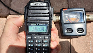
Now what does the title of this topic relate to?   A few weeks ago I noticed that one of my Diamond X50 UHF/VHF Antennas was completely "deaf".  I could not receive the 145.750 Mhz Aasvoelkop Repeater which is situated just outside of Albertinia a distance of about 35 km from my QTH.  In the past I could hear this repeater clearly with this specific X50 antenna, but with some rain on the signal.   The other Diamond X50 is connected to the GRHub Network link radio and performs as it should.  This antenna is 12 meters up in the air while the "deaf" antenna is two meters above my roof making the total height of this antenna above ground, 6 meters. The GRHub X50 was apart from the factory sealing also coated with  Tectyl Glashelder Klar a transparent rust preventive clear spray. (Been successfully using this for years to seal and coat my antennas against natures elements) The "deaf" antenna was not and was installed  with no protection at all.  The day before I decided to take the "deaf" antenna down I did a quick test.  You guessed correctly, no RX from the 145.750 Mhz repeater at all.  A further puzzling factor was that the SWR reading was 1.2:1 but would drop to 1:1 .  Power output was in spec with the radio's RF power output.  Mind boggling?  This antenna was now really "deaf" and needs to be looked at.

Once the antenna was on the ground I was quite surprised to see that natures elements at the sea was really minimal despite the fact that the antenna was up in the air for 2 years 3 months.  Hereunder a few images of the antenna before refurbishing:  (Click on images for larger view.)


I opened the antenna to see if the high voltage capacitor was not fried.  The capacitor was fine and there were no dry joints.  No corrosion or any signs of dampness/water penetration could be seen or found.  The inside of the antenna was in great shape.  What I did find was the the Allen Key Grub Screw was loose and did not make contact with the antenna connector.  I fitted all the insides and tighten the grub screw firmly.  I installed all the necessary parts and affix the antenna to my portable mast.  Here under a few images of the antenna under testing: (Click on images for larger view.)


Testing with the above equipment is not ideal but that is all I have.  The tests reveal that the antenna is now working as it should.  I could trigger and receive the 145.750 Mhz repeater with the antenna just above the Parrot cages, which was far lower than before.  The Diamond X50 Antenna was no longer "deaf".

The images underneath reflect the antenna after refurbishing:  (Click on images for larger view.)


The Verdict:

I could not find anything wrong with the antenna nor the coaxial cable.  The only issue that I found was that the Grub Screw that keeps the antenna connector affixed to the 3 x  radial connector was loose and therefor their was no continuity between the radiating element and the "ground plane" connector of the antenna.  Windy conditions would either result in a good or bad contact which might not have been the case when I used the deaf antenna. Whether the loose grub screw  resulted in the deafness of the antenna is the only conclusion that I could come to.   RF is a wonderful and mysterious element that could result in many good or bad issues.

A bit of sound advice that might be of assistance to other Diamond users:

  • When you assemble the antenna ensure that all bolts, nuts and grub screws are tighten properly. Never assume like I did that the grub screw was tighten at the manufacturing plant.
  • I would suggest you use additional sealant to protect the antenna from natures elements.
  •  Never use a sealant or grease that contain other metal elements like copper slip crease etc.  Metal elements like copper, aluminum, stainless steal inter act with each other and hasten metal erosion and fatigue.
  • Use a bit of marine grease on all bolts and nuts that screws into parts.  Not on outer parts as the Tectyl will not adhere to the items. This will prevent nuts and bolts getting stuck due to corrosion.
  • I suggest that you service (refurbish) this and other antennas at least once every two years
  • Seal the PL259 that screws into the antenna with self amalgamating tape.
  • Ensure that you have the correct type of Diamond Antenna for the area you live in.  If you live in the "Cape of Storms" area I would not recommend large "oversized" antennas as the wind will definitely rearrange the antenna for you, resulting in damage. loss etc.

Finally: 

One is never to old to learn about antennas.  Many of us can oversee a small aspect that will result in the antenna not working as it should.  Be very precise and meticulous when mounting and installing antennas and you will have many years of pleasure from your antennas.  Remember maintenance is very important.  Nothing last and works forever but you will extend the life of an antenna by thoroughly maintaining it.  Enjoy!!


New ZS6CM0 70cm AllStarLink Repeater - Alberton

(Click on images for larger view.) Curtis ZS6CMO recently completed his 70cm AllStarLink Repeater.  In the video the repeater was connected ...