Showing posts with label Power. Show all posts

Thursday, June 26, 2025

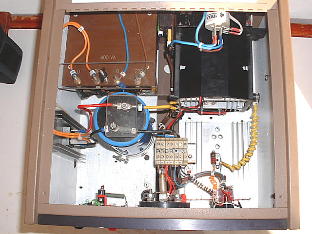
Down Memory Lane: Variable Power Supply Project by Chris Meyer ZS1M - June 2003

Image:  Chris Meyer ZS1M  (Click on image for larger view)

Chris Meyer ZS1M a well known radio amateur in the Southern Cape constructed a 0 - 30 Volts, 20 Amp Variable Power Supply in June 2003. Looking at the photos this is a very neat and well constructed power supply by Chris ZS1M.  Although Chris is not active on the airwaves anymore, he was always a good source for various types of components and old used radio equipment. Sadly time moves on and Chris disposed of all his surplus components and equipment.  Chris was also instrumental in obtaining a permanent repeater site for the 145.600 Mhz Repeater on the Dana Bay water tower.  No wonder the 600 repeater was known as the Dana Bay Repeater.  This repeater played a instrumental roll for many years in the Mossel Bay area.

Apart from the amateur radio hobby Chris also wrote several books relating to genealogy especially related to the Meyer Family. Chris also documented information about many local cemeteries in the Mossel Bay district. He also wrote a booklet about the history of the Garden Route Radio Club. 

Best wishes goes to Chris ZS1M and Bets his wife during their Golden Years.


Monday, May 5, 2025

12 v High Current DC Power Supply Project for your Amateur Radio Equipment


A R65.00 DC Power Supply Project for your Amateur Radio Equipment.  Can this really be true?   Read on and find out.

A year or so ago I ran into three old Dell PowerEdge Servers at an auction for R50 each.  Nobody wanted them and I took them home.  All three were in a working condition but were fairly old technology.  I stored them in my container for a "rainy day".  Well the rainy day arrived in April 2025 when I ran into a short article how to convert a server power supply into a low noise 12v DC Power Supply.  Server power supplies are noisy and when the fans run at full speed it sounds like a turbo jet. Very very noisy indeed!

I intended to scrap two of the servers and keeping the smaller one for another "rainy day".  After stripping of the servers I was left with many usable parts.  I looked at the 4 x power supplies and realized that the one server's supplies does not have fans embedded in the power supply casing.  However these two units were fed with air that circulated inside the server.  These two looked like good candidates to modify into a low noise 12v DC Power Supply for Amateur Radio Equipment.

Here are some images of what the Server Power Supply looked like before any modifications.  (Click on images for larger view.)


Herewith the specifications of the Dell Model D670P-S0:

Dell D670P-S0 SERVER POWER SUPPLY

The Dell D670P-S0 is a 670W power supply unit (PSU) with a 100-240V input, designed for Dell PowerEdge 1950 servers, and features a 54.4A +12V output and a 5.25A +3.3V standby. 

Here's a breakdown of the Dell D670P-S0 power supply specifications: 

  • Model: D670P-S0

  • Power Output: 670W

  • Input Voltage: 100-240V

  • Input Current: 10A / 200-240v 4.8a

  • Frequency: 47-63Hz

  • Output:

    • +12V: 54.4A

    • +3.3V Standby: 5.25A

  • Designed for: Dell PowerEdge 1950

  • Other Notes:

    • Hot-plug capable

    • May be used for 12V bench supply with some modification

    • Requires jumper connections to enable 12V output

    • Jumper pin A1 to A3 (ground)

    • Jumper from B6 (12V power enable) to B3 (ground)

WARNING:  Please note that all server power supplies does not have the same jumper pin and power outputs.  Ensure that you have all the information of the server power supply you want to modify.  If not sure then do not go ahead with the modifications.  Take care when working with any power supply as high voltages are present that are lethal and will kill you if you make mistakes or by accident.  You have been warned!!

TAKE NOTE:  For use as a power supply for Amateur Radio it may be best that the case be left connected to -12v.  This may help to reduce RF noise from the switching power supply but experimentation will have to be done as to the best way to eliminate the RF.  Interference will not be an issue on VHF radios but on HF radios the lower bands might be affected and is so RF filtering will be required.

Before I continue to explain how I went about to modify the Dell D670P-S0 Server Power Supply it is necessary to make mention of the fact that this project is not my idea or invention.  I visited several Internet sites to gather information to undertake this project.  There are an abundance of information on the Internet in this regard.

If you plug in the 220v AC plug the unmodified server power supply will not produce any 12 v output. We need to install jumper connections to enable 12 v DC output.  Lets look at the pin header that will host the jumper connections.

Image:  Pin Header (Click on image for large view.)

STEP 1:  Enable other Futures

For the Dell D670P-S0 power supply we need to jump pin A1 (plugged in) to A3 (ground)  This jumper does not seem to alter power supply state in any way, other than to enable other features to work. There is no reason not to make this connection permanent if the supply is no longer being used in a Dell chassis.

STEP 2:  Enable Main Power Output

Jumper from B6 (12V power enable) to B3 (ground). This should enable the main power outputs.  We will be adding an OFF / ON Toggle Switch between these two pins.


STEP 3:  Pin Diagram - Other Features

I use female DuPont cable sets for connecting the pins. They fit tightly and prevent any short circuiting to other pins. I added the off/on switch at a later stage as I wanted to see if the server power supply would startup correctly.

Now that we have all the pins connected it is time to add 220v AC to the input and measure the output voltage at the PB connectors.  After switching on the 220v AC Input and a few seconds later the 12V DC Output came to life.

Take note that this power supply has no fan, so do not let it run for long periods until you installed a fan.  The supply can get hot quickly and we do not want to damage the supply before all the modifications have been completed.

The next awkward modification is to modify the - Neg and + Pos connecting pins.  I tried to solder thick copper wire to the PB pins but solder would not take on these pins.  Now either the pins were very dirty or my soldering iron was on the cold side.  Instead of trying to clean the pins or stuff up the pins I decided to use electrical female spade connectors that fits nicely over the PB pins.  I soldered thick copper wire to the spade connectors and plugged the negative and positive "connectors" into the server power supply.  Joining the outputs together like I did will provide 54 Amps of current.  You can also make three output connections giving you about 18 Amps individually. 


Once this modification is complete you may solder the output wires (Black + Red) to the thick copper wire and you are ready to use the power supply. If you tied the outputs like in the image above use 4.8 mm wire @ 54 Amps .  If not tied use 2.6 mm wire @  3 x 18 Amps. 

I wanted something that looked better and that protects all the connections, furthermore the fan needed to blow all the air through the supply.  Leaving it open will not provide sufficient air flow.  I found a 3D printer cover for the server power supply.  After printing the cover on my 3D printer I was not happy with the strength, thickness and cover distance of the cover.

I decided to roll my own cover with Free-CAD and printed the cover on my 3D printer.  I added the On/Off switch between B3 and B6.  As mentioned before this server power supply has no fan to keep it cool.  No problem!  I took one of the server fans but from experience I know that when these fans run at full speed they make a heck of a noise.  To curb the noise but still have a decent amount of  airflow in the server power supply, I had to either control the the fan using a thermal switch or install a switch between B2 and B3. Open is Hi,  Closed is low.

I however choose the easy way out by adding a resistor in the positive line of the fan.  I used a 47 Ohm 5 watt resistor.  You can play around with the value of the resistor but ensure that you use a 5 watt component as this resistor gets fairly hot.  To keep this resistor as cold as possible I mounted it on top op the pin connectors where the fan can furthermore keep the resistor and the power supply unit cold.  This is an easy solution and worked like a charm.


After all the connections was made I used the hot-glue gun to "isolate" them.  Furthermore the hot-glue prohibit the wires from breaking off or become loose.   Next I installed the fan, switch and black compression glands.  It took some effort to fit everything through the open end but I managed to complete the task.  Next time I will re-design the 3D cover to make it easy to fit all the parts and components.

Once again time to test the modified server power supply.  The end result is a working 12.37v DC,  54.5 Amp power supply.  Most of the server power supplies do have different protection circuitry, however I chose to add my own Crowbar Unit to this supply for "extra" protection.  More on this project, click HERE.

Finally:  Total cost of this project amount to R65.00 (excluding the add on Crowbar Unit.)  I will test this supply further and will do a follow up article on my findings.  So far I think all the effort was worth it and I am now the proud owner of  a high current DC power supply.

Images:  (Click on images for larger view.)


Thursday, April 24, 2025

DIY Overvoltage Crowbar Protection Circuit Project (Project 2)


(Click on image for larger view.)

I always seem to look for a simple crowbar circuit to protect my radios and other electronic equipment from over-voltage and reverse polarity.  Now I know there are many types of crowbar circuits that provides many types of protection.  I did not want to "re-invent the wheel" relating to crowbar circuits. In Project 1 I used the well known MC3423 Chip and a few other components.  More information available HERE.

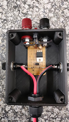
In the images below is a protection circuit I found on the Internet. It blows the fuse if the voltage from the power supply rises above 15 Volts. It uses a 20 Amp thyristor so it’s more than capable of blowing a 15 Amp fuse. I’m using a 10 Amp fuse because that’s all I had. Also, most of my equipment running from this power supply aren’t current hungry. (More on the modified power supply in a future posting.) By the way, I wouldn’t rely on the modified power supply’s short circuit protection to cut the power.  I decided to use fuses instead of using a relay.  Once again some say a relay is better than a fuse.  I used what I had on hand!

I decided to add a TVS diode (transient voltage suppression diode) as used in the original design, as this would appear to make the BT152 thyristor redundant. If the TVS diode conducts at 15 Volts then, why use a thyristor? Well why not use double protection?  I suppose the TVS diode is fast when dealing with transient voltages. The TVS diode also protects against an accidental reverse polarity voltage connection. 

Now before you running of to build the Crowbar a word of warning!!  Using Vero Board is fine, but do bear in mind that the thin copper strips are not designed to carry 20 or 30 Amps! To solve this problem, I ran 3mm tinned copper wire alongside the heavy current-carrying strips. I also joined (soldered) clean tracks together that carry the 12 Volt in/out of the board.  The board can now easily carry the 15 Amp current without any issues.  If you upscale the Thyristor and other components for higher current then I would advise not to use Vero Board.  Dead Bug Style or a PCB might be considered. 

Parts List:

1.5KE 15 TVS 1.5kW 15v Diode

BT152 Thyristor 800v 20 Amp

27K 1 watt Resistor

10 Ohm 1 watt Resistor (I used a 2 watt that I had)

1 uF 50v Radial Electrolytic Capacitor

1N5245B Zener Diode 15v 1 watt

Vero Board (65mm x 35mm)

Red and Black Flex Wire (Copper diameter = 2 - 3 mm)

Optional:

Black and Red Terminal Posts

2 x Fuse Holders

2 x 10 Amp Fuses

1 x LED Holder

1 x Red LED

1 x 330 Ohm 1/4 watt Resistor for LED

1 x Project Cabinet

1 x Black Compression Gland 12.5mm CAB = 4-8mm


(Click on image for larger view.)

Construction:

Constructing this Crowbar is straight forward as indicated by the diagram and images.

Information on the two fuses.  I used normal automotive fuses which I had in my component cabinet.  I would however advise using good semiconductor fuses on the 13.8v input line to protect the SCR.  The I2T rating of the fuse should be less than that of the SCR.  You have been warned!!

What is a Semiconductor Fuse? Also known as ultra-rapid fuses, high speed fuses or rectifier fuses; a Semiconductor fuse is a high speed current limiting fuse that is designed to protect and isolate sensitive semiconductor components such as diodes, thyristors, SCRs etc. by minimizing the I²t, peak current let-through and arc voltage.

Summary:

I recommend you construct this unit that provide over-voltage and reverse voltage protection and fusing. This unit will ensure that your equipment is protected from inadvertent power supply transients, power supply over voltage failures or connection mistakes like reverse polarity. 

Note:  I will provide more information about the working of the Crowbar in a future article.

Images:  (Click on images for larger view.)


Thursday, November 28, 2024

An "Outboard" Over Voltage Protection Project for a Power Supply


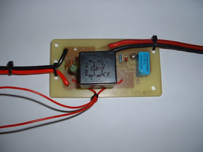
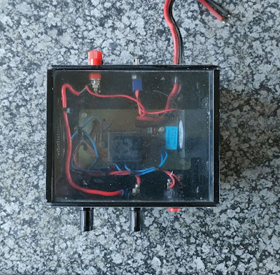
I built this project in February 2004 and it appeared in QSX the monthly newsletter of PEARS.   I decided to give it a decal makeover as the 2004 Letraset decals looked rather old and worst for wear.

I know that there are many articles in the past in QSX relating to the above project.  However after constructing the Heavy Duty Power Supply described by Andre Botes ZS2ACP in QSX I decided to look at the over voltage protection circuitry.

A thought came to mind that a separate PCB that hosts the over voltage protection components could come in handy especially if you have a power supply with no such protection.  I changed the PCB outlay to suit my needs and come up with a board as shown in the image below. (Not to scale)  As this is a simple project, I will  not go into all the detail to construct the protection unit other than providing you with the component overlay and a few photos of the project amongst the images below.

Just a word of advice:  Use thick wire on the input as well as the output side depending on the amount of current (amps) your power supply provides.

This handy little unit could save you a lot of tears and money if your power supply decide to go into over-voltage- or short circuit mode.  

Images:  (Click on images for larger view)

Component List:

    1. Green LED
    2. 1K2 Resistor
    3. Relay 30 AMP AUTO 12 Volt
    4. Relay TAKAMISAWA RY5W-K  5 Volt
    5. Push Button
    6. BC 108 OR BC 109
    7. 1K Resistor
    8. 13V Zener Diode
    9. 10K Resistor
    10. 470 Ohm 5 Watt Resistor
    11. 0.01 Capacitor
    12. 0.0001 Capacitor
    13. 0.1 Capacitor
    14. 470 Ohm Resistor
    15. Red LED


New ZS6CM0 70cm AllStarLink Repeater - Alberton

(Click on images for larger view.) Curtis ZS6CMO recently completed his 70cm AllStarLink Repeater.  In the video the repeater was connected ...