Showing posts with label Digital Modes. Show all posts

Sunday, August 31, 2025

The AMSAT SA and SARL Meteor Scatter Communication webinar recording is now available on YouTube


Video: AMSAT SA  (Click on image to view video.)

Have you ever imagined bouncing your signal off a shooting star? As radio amateurs, we don’t have to rely on satellites or repeaters to reach distant stations—sometimes, the natural phenomenon of meteors blazing through our atmosphere gives us the perfect reflector. This fascinating technique is called meteor scatter communication. 

The AMSAT SA and SARL Meteor Scatter Communication webinar recording is now available on YouTube by clicking HEREThe webinar was presented by AMSAT SA and the SARL to promote interest and participation in Meteor Scatter Communication. The presenter was Derek Gravett ZS5Y with guest participation of Frank Schneider ZS6GE. In the presentation, Derek Gravett, ZS5Y, explains how meteor scatter works, why MSK144 has become the preferred mode for modern radio amateurs, and the practical setup you need to start making your own “cosmic” contacts. Just imagine bouncing your signal off a shooting star. As radio amateurs, we don’t have to rely on satellites or repeaters to reach distant stations, sometimes, the natural phenomenon of meteors blazing through our atmosphere provides perfect reflection. This fascinating technique is known as meteor scatter communication.

MSK144 is part of the WSJT-X suite, developed by Nobel laureate Joe Taylor, K1JT. It uses fast, efficient minimum-shift keying to capture those fleeting bursts of reflected signals from meteor trails bursts that may last only fractions of a second. With this mode, VHF and UHF operators can achieve contacts of 500 to 2 000 kilometres or more, even when the bands seem completely dead.

- AMSAT SA & SARL

Tuesday, June 17, 2025

Let's build a KISS USB Soundcard Interface for Digital Modes (Part 1)


Through the years I have build many types of Soundcard Interfaces.  Some KISS models and others with micro controllers.  You can find some of the interfaces HERE. They all enabled me and many others to work various digital modes.  Nowadays many of the new radios do not need the conventional soundcard interface to allow you to work digital modes.  Several years ago I found The USBLink design by Julian Moss G4ILO  now SK.  I kept a copy of his article on my Soundcard Interface file for many years long before Julian went silent key.  About two weeks ago I paged through my file and found the article.  Now I do have several types of Soundcard Interfaces in my shack but this interface article gave me an idea that I will discuss in Part 2.  First off I need to build the USBLink Interface and test it live on the air.   The article of the USBLink is available HERE.  

This interface is in my opinion a KISS unit with no bells and whistles.  Herewith a few features that makes the unit a KISS interface:

1.  No Serial to USB interface / cable needed to handle PTT.

2.  No 1 : 1 (600 ohm) isolation transformers needed.

3.  Relatively low cost to construct the unit.

4.  Relatively small size compared to other homebrew interfaces. (Ideal for portable operation.)

5.  Does not use opto-isolation of the PTT line. (Not needed)

6.  Inexpensive USB Sound Card can be used. (Chinese cheapies will also work but I would rather buy a better quality product.)

7.  Project can be constructed on a piece of veroboard.

8.  No dedicated power supply needed for the Soundcard Interface.

9.  Diodes added for PTT transistor and radio protection. (I would however add another switch to cut off the PTT line going to the transceiver to prevent accidental PTT activation when unit is left unattended.)

10.  Plug and Play Unit - No drivers to install.

Finally:  This is a simple low cost circuit which works well and allows you to operate sound card digital modes without tying up your computer's built-in sound card.  I constructed this interface and tested the interface on VHF.  In part 2 I will provide feedback on how the interface behave on HF but from what I observed using a VHF transceiver it should work just as well on HF.  Although I am not in favor of using VOX in any way in amateur radio, I do not foresee any issues using this interface attended.  I would not leave this interface unattended and therefor suggested the additional switch  between ground and PTT to prevent accidental transmissions.

Images:  (Click on images for larger view.)


Monday, May 19, 2025

How I setup my Yaesu FT817 Radio and Homebrew Arduino Soundcard Interface (SignalLink Clone) to work Digital Modes


During the PEARS VHF/UHF Contest that took place in January 2025 I decided to setup my trusted Yaesu FT 817 Radio using my Homebrew  Arduino Soundcard Interface to work a few digital mode stations.  In a previous article available HERE I explained another type of homebrew interface that includes the CAT control.

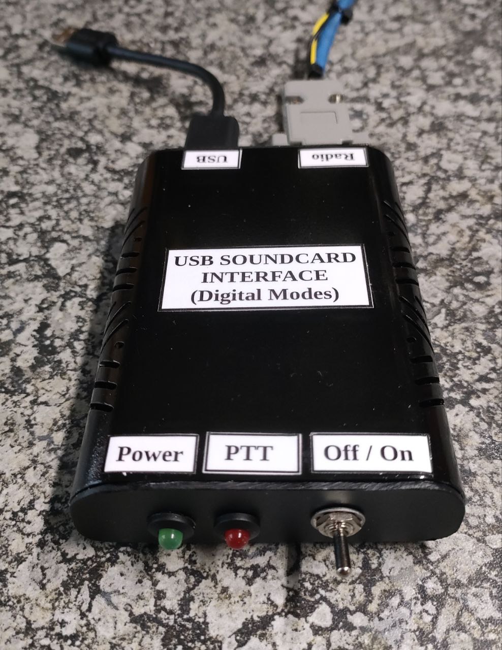
The Arduino Soundcard Interface I am going to describe can be used with many types of radios.  This interface function the same as the commercial available SignalLink Interface, therefor the reason that it is called a SignalLink Clone.

The FT817, 857 and 897 radios have a few settings that must be setup correctly,  if not then you will not be able to play with digital modes.

Please take note that the setup explained worked for me. 

My Setup:  ( Yours might differ depending on the equipment you use)

Setting up the Computer and Software:

DO NOT switch the Yaesu FT817 or the computer ON.  
We first need to plug in all the cables.
Plug the USB cable coming from the Soundcard Interface into a USB port on the computer.
Plug the FT817 Mic Cable coming from the Soundcard Interface into the mic socket of the FT817
Plug the 3.5 mm Extension plug into the SP Ext. Socket on the FT817
The switch next to the 3.5 mm socket must be set to SP = Speaker
Plug antenna and radio power cord in
Ensure the correct antenna port is selected.  Either front or rear.  (Menu #7)
Now power up the computer and the FT817 Radio
Radio and Interface should now be ON
Set frequency on radio.  In this case we start with VHF and FT8 = 144.174 MHz USB
Now start the WSJT-X Program 

WSJT-X Setup:

Go to file settings - Radio
CAT must be OFF if you not going to use CAT = Rig:  NONE
PTT Method = VOX
Click on Audio TAB

Soundcard:

Input:  Microphone (32-USB PNP Sound Device)
Output:  Speakers (32-USB PNP Sound Device)
Input = Mono
Output = Mono
Click OK

In WSJT-X:

Monitor Button should be green and  O next to the band should also be green.  Radio and WSJT-X are talking to each other.  If not then check Hardware and Sound.
Control Panel =  Hardware and Sound.  Select Manage Audio Devices in Windows computer
New window will open named:  Sound with playback displayed
Double click on Speakers
Speaker Properties will open
Go to Levels

Speakers 98 Balance
Microphone 68

Click OK

Go to Recording TAB
Double click Microphone
Microphone Properties will open
Go custom. AGC must not be selected
Go to Levels

Microphone 50
Click OK

All other Playback and Recording devices must be DISABLED!
Voicemeeter Banana must not run at all if you have it installed!

That should be it for the computer audio settings.

Now for the Yaesu FT817 Radio Setup:

Press F for more than 2 seconds
We are now in the MENU of the FT817
Rotate teh SEL knob on radio (left side) to select menu 1 - 57

Setup the following MENUS for the Arduino Soundcard Interface as follows:

# 3  9600 Mic = 50
# 7  Antenna = Front or Rear
#14  Cat Rate = 9600  (If used)
#24  Dig Disp = 0 hz
#25  Dig Mic = 70
#26  Dig Mode = user-u
#27  Dig Shift = 0 hz
#29  FM Mic = 50
#38  OP Filter =  OFF (CW or SSB Filter)
#39  PKT Mic = 50
#40  PKT Rate = 1200
#45  SQL/RF-G = SQL (VHF) (RF Gain for HF)
#46  SSB Mic = 50
#51  Vox Gain = 50 (If used)
#52  Extend = ON
 
MODE =VHF/UHF = FT8 144.174 Mhz USB (USB work in VHF)
To check if equipment is setup correctly we are going to use an SDR Receiver Dongle installed on another computer.  Start the SDR computer with the RTL plugged into a USB port.  Open OpenWegRX program.  Once open select RTL-DDR 2m Voice Repeaters.  The 2m band will be displayed.  If you can hear white noise and signal meter works, go back to the computer with WSJT on it.  Click on the Tune button in WSJT-X.  Radio should TX and a line will appear on the window (waterfall)  Move the yellow ^ marker exactly on the line in the waterfall.  You will hear the tune signal clearly and your RX bar will go to red.  This means you are on the frequency of your radio that is in TX mode.  Stop Tune.
Select USB in Modes and click on the down arrow.
 
Select FT8 and two screens will open while DIG in the modes will turn yellow.  On screen = waterfall and other display station info.   Now enable TX on WSJT-X using FT8.  You should hear FT8 clearly in OpenWebRX.  Decode box in OpenWebRX will display CQ info:
 
UTC               dB    DT        Freq       Message
 
08:58:00         1      0.2     144.175    CQ ZS1I KF15
 
That's it your TX signal is now going out on the airwaves and being received by OpenWebRX
 
You are now ready to make your first QSO on VHF with the Yaesu FT817 Radio and the Arduino Soundcard Interface.
 
As said previously the above settings worked for my setup.  Your setup might differ but I am sure that some of the information in this article will be useful in setting up your Yaesu FT817, 857 or 897 radio to work digital modes.
 
You should now be able to work digital modes with the Yaesu FT817 Radio.  

Enjoy working digital modes in amateur radio!!           

General Checks and Settings:
 
1.  Set MTR ALC  Press F once, select MTR ALC by pressing B.  This will reflect ALC when in TX mode.
2.  Check antenna Input = Front or Rear  MENU =  #7  (Select socket where your antenna is plugged in.)
3.  Check SWR Meter (PWR and SWR)
4.  Check receiving meter (WSJT-X)  Must be in the green between 40 - 60 dB.  If in the red adjust recording level - microphone to a lower setting until meter is in the green.
5.  Add  Fan to the back o the Yaesu FT817 to prevent the radio from overheating.
6.  From time to time the FT817 screen will warn you of high SWR = SWR High.  If your antenna is tuned correctly check all other connections that they are tight.  Check also all patch leads for good connectivity.  Check if the radio is cutting power and if the warning comes up between voltage and mode.  You can also try to use the other antenna socket on the radio (Front or Rear)  This anomaly happens from time to time especially if the radio is moved around or used in portable mode.
7.  Never forget to have the FT817 Operating Manual in close proximity.  You will need it more than you think.
 
Images:  Click on images for larger view.
 
NOTE:  The Arduino Soundcard Interface needs an urgent facelift.  Hopefully I will find some time to re-spray and label it properly.


Saturday, April 12, 2025

Aasvoëlkop Repeater site in the Southern Cape gets free Internet Connection


Image:  AasvoĂ«lkop Repeater, Albertinia, Southern Cape

The AasvoĂ«lkop Repeater site in the Southern Cape has once again been upgraded with the addition of a FREE sponsored Internet connection provided by Whisper Net.  Thanks must go to Vivian Louwrens ZS1VIV who led the negotiations with the above service provider.  If it was not for Viv then this valuable free Internet connection would not have been a reality, especially if you take the location of the AasvoĂ«lkop site into consideration.


Image:  Whisper Net Coverage Area  (Click on image for larger view.)

Some of the purest of the pure might say but this is no big deal as it is just  an Internet connection which is in any case not amateur radio.  I would like to invite those to look what benefits the Internet would bring to a repeater site in general.  If you want to explore and experiment with new technology today you cannot be without the Internet and computers.  Both has become part and parcel of amateur radio.  Enough rambling let's look at some of the possibilities such a connection might bring to the site:

1.  Installing IP cameras on site for additional security for the AasvoĂ«lkop Repeater.

2.  Installing IP cameras to monitor a wide circle area to spot veld-fires, severe weather conditions, thunderstorms and lightning etc.

3.  Installing a Digital Weather Station linked to the Internet that provides a wide variety of data like, Temperature, Rainfall, Wind Speed, Wind Direction  etc.  One can even install censors to detect and monitor pollution and other atmospheric conditions.

4.  Install an Aviation ADS-B (Automatic Dependent Surveillance-Broadcast). ADS-B system that broadcasts aircraft location and other information to other aircraft and ground stations.  A great service to the aviation and public communities in the Southern Cape and World Wide.

5.  Install an Automatic Identification System (AIS) that is a short-range coastal tracking system currently used on ships. It was developed to provide identification and positioning information to both vessels and shore stations.

6.  Linking the AasvoĂ«lkop Repeater to various other local repeaters in the Southern Cape via Echolink, AllStar, DMR Bridge or SVXLink.  Although currently not needed the option is always available.

7.  Linking the AasvoĂ«lkop Repeater to Amateur Radio Emergency Data Network (AREDN) which is currently operational in the Mossel Bay area.

8.  Installing an Amateur Radio Emergency Data Network (AREDN) Node on the AasvoĂ«lkop Repeater tower that will provide amateur radio emergency communications when needed.

9.  Installing a HF Remote Radio Station on site. A remote HF station allows amateur radio operators to control their radio equipment from a location away from the radio shack.  Especially handy for those radio amateurs that cannot install antennas at their QTH.

10.  Installing a cloud server on site for the 625 Amateur Radio Group use.  

I am sure there are many other options available not mentioned above.  But from the above one can see the benefits of having a Internet connection on the AasvoĂ«lkop Repeater Site.  Work on-site will begin shortly to install the Internet connection to the repeater site.

Finally:   Once again a big thank you to Whisper Net, Viv ZS1VIV,  Johann ZS1AAC and all the other helpers that will assist to get the connection to the repeater site.  Look out for future updates in this regard.

Image:  Whisper Net  (Click on image for large view.)

Saturday, March 8, 2025

Important message for Brandmeister - i.r.o. radio amateurs using a Radio ID starting with 1


 The Brandmeister DMR platform is a constantly evolving system, requiring regular optimizations and maintenance to ensure its efficiency, reliability, and alignment with global open standards.

As part of these ongoing efforts, we are addressing an issue that arose seven years ago regarding the assignment of improperly numbered Radio IDs. As announced at that time, Brandmeister stopped importing invalid Radio IDs and requested that hams with such numbers obtain a new, properly formatted Radio ID.

To facilitate operations, scripting, and automation on Brandmeister, we are now starting the complete removal of Radio IDs that do not comply with the internationally recognized MCC (Mobile Country Code) numbering system.

If you currently have a device connecting to Brandmeister with a Radio ID starting with the digit “1”, please read the following carefully:

  • 7-digit personal radio IDs starting with 1 (such as 1030512) will stop working on Brandmeister after January 1st 2026. If it is inactive for more than a couple of months, it will be purged sooner.

  • 6-digit repeater radio IDs starting with 1 (such as 102765): while we don’t have a set date for deprovisionning these IDs, we are urging sysop to migrate to a 31xxxx ID as soon as possible. If the repeater is offline for an extended period of time, it will be purged and will require a new properly formatted ID to re-connect.

  • 5-digit CAP+ IDs will stop working on Brandmeister by June 1st 2025.

IDs are issued by Radioid.net, if you have an ID starting with 1, you need to log into your RadioID account and open a ticket requesting that your ID number be replaced with one starting with 3

Jan 28th update: RadioID added a feature to automagically convert your 1xxxxxx (1n) ID to the 3xxxxxx (3n) format:

  • Login to your RadioID Dashboard

  • Click on the 1n ID.

  • You will then see a button to Convert to 3n. Click it.

  • Once done, you will be returned to your dashboard and have a new 3n ID

For assistance, you may contact RadioID support at https://radioid.net/support

Best Digital 73’s !

BRANDMEISTER

Monday, March 3, 2025

How I setup my Yaesu FT817 Radio and Homebrew Soundcard Interface to work Digital Modes

Image:  ZS1I Yaesu FT817 Radio

Image:  ZS1I Homebrew Yaesu FT817 Soundcard Interface

During the PEARS VHF/UHF Contest that took place in January 2025 I decided to setup my trusted Yaesu FT 817 Radio using my homebrew soundcard interface to work a few digital mode stations.  The FT817, 857 and 897 radios have a few settings that must be setup correctly,  if not then you will not be able to play with digital modes.

Please take note that the setup explained worked for me.  I did not use the CAT on this occasion as I need to buy the necessary accessory plug before I can use CAT. 

My Setup:  ( Yours might differ depending on the equipment you use)

Setting up the Computer and Software:

DO NOT switch the Yaesu FT817 or the computer ON.  
We first need to plug in all the cables.
Plug the USB cable coming from the Soundcard Interface into a USB port on the computer.
Plug the data cable coming from the Soundcard Interface into the Data socket of the Yaesu FT817. (Back of the radio.)
Now we can switch the radio on and then the computer.
The radio, computer and interface will now be be ON.
Start WSJT-X by clicking on the icon in your desktop or program start menu.
Go to File and then click on Settings then Radio.
CAT must be OFF  -  Rig = NONE
PTT Method = DTR Port:  Com3
Next click on Audio 
Here we will setup the Soundcard to be used

Soundcard:

Input:  Microphone (19-USB Headphone Set)  -  Left
Output: Speakers (19-USB Headphone Set)  -  Both

Click OK

Monitor Button should be green and round   0 should be green.  Radio and WSJT-X are now talking to each other.  If not check your hardware and sound on the computer.

Select:  Go to Control Panel. Click  on Hardware and Sound and then on Manage Audio Devices.  Sound window will open with Playback displayed.  Note: If you do not use VoiceMeeter then ignore those settings.

Playback:

Speakers:  19-USB Headphone -  Ready
Speakers:  Behringer USB - Disabled
VoiceMeeter Aux Input - Default Device

All others disabled

Recording:

Microphone: 19-USB Headphone - Ready
Line In:  Behringer USB - Disabled
VoiceMeeter Aux Output - Default Device

All others disabled

Managing Devices:

To set the level of the devices go back to Playback and double click on Speakers.  
Select Levels.  
 
Set levels as:

Speakers 83 
Main volume 83
 
To set the level of the devices go back to Recording and double click on Microphone (or Line In)  Select Levels.
 
Set levels as:
 
Microphone 82 
AGC MUST BE OFF!!

Go back to Playback
Select VoiceMeeter Aux Input (Double Click) 
Select Levels

Set levels as:
 
VoiceMeeter Aux Input = 100
Main Volume = 93
 
Click OK

Go to Recording and double click on Voice Meeter Aux Output
Select Levels

Set levels as:

VoiceMeeter Aux Output = 89
Wave in Volume = 100

Click OK

We completed the setup of sound on the computer.  Now we need to setup VoiceMeeter Banana

Open the VoiceMeeter program
 
Hardware Input 1 =  Behringer USB Audio
Hardware Out = Behringer USB Audio
 
Select the above if not displayed in VoiceMeeter.  Restart VoiceMeeter once selected.
 
Setting up WSJT-X Program:
 
I am not going to explain setting up the WSJT-X software as there is a complete manual explaining how to install and setup WSJT-X.  Please use the manual.

Setting up the Yaesu FT817 Radio to work digital modes:

Press F for more than 2 seconds
When in MENU rotate the SEL knob on radio to select menu 1 - 57
Set the following Menus:

# 3  9600 Mic = 50
# 7  Antenna = Front or Rear
#14  Cat Rate = 9600  (If used)
#24  Dig Disp = 0 hz
#25  Dig Mic = 70
#26  Dig Mode = user-u
#27  Dig Shift = 0 hz
#29  FM Mic = 50
#38  OP Filter =  OFF (CW or SSB Filter)
#39  PKT Mic = 50
#40  PKT Rate = 1200
#45  RF Gain/SQL = RF Gain (Digital)  SQL FM
#46  SSB Mic = 50
#51  Vox Gain = 50 (If used)
#52  Extend = ON
 
MODE =  DIG in SSB
             =  PKT in VHF/UHF

General Checks and Settings:
 
1.  Set MTR ALC  Press F once, select MTR ALC by pressing B.  This will reflect ALC when in TX mode.
2.  Check antenna Input = Front or Rear  MENU =  #7  (Select socket where your antenna is plugged in.)
3.  Check SWR Meter (PWR and SWR)
4.  Check receiving meter (WSJT-X)  Must be in the green between 40 - 60 dB.  If in the red adjust recording level - microphone to a lower setting until meter is in the green.
5.  Add  Fan to the back o the Yaesu FT817 to prevent the radio from overheating.

As said previously the above settings worked for my setup.  Your setup might differ but I am sure that some of the information in this article will be useful in setting up your Yaesu FT817, 857 or 897 radio to work digital modes.
 
You should now be able to work digital modes with the Yaesu FT817 Radio.  

Enjoy working digital modes in amateur radio!!
 
 
Images:  (Click on images for larger view.)


New ZS6CM0 70cm AllStarLink Repeater - Alberton

(Click on images for larger view.) Curtis ZS6CMO recently completed his 70cm AllStarLink Repeater.  In the video the repeater was connected ...