Saturday, December 31, 2022

Terugblik op die Verlede / Down Memory Lane “OSRAM BERG TYDREN” 14 AUGUSTUS 2004 deur Johan Terblanche, ZS1I

Die taaiste en veeleisendste tydren in Suid Afrika? Ja, dit is hoe baie deelnemers die “Mountain Trail” tydren bestempel wat jaarliks in die Aliwal-Noord, Barkly-Oos omgewing gehou word. Ek het die jaar die voorreg gehad om as waarnemer deel te vorm van ‘n span radio-amateurs wat verantwoordelik was vir kommunikasie tydens die tydren.  Ek praat hier van die Bloemfontein
Radio Amateur Klub.


 Dennis Green, ZS4BS, was die hoof-organiseerder gemoeid met radio kommunikasie. Hy het dan ook stelling ingeneem by die tydrenkoofkantoor wat ’n uitsig gehad het oor die Garieprivier (sien
foto hierbo).

Vervolgens ’n opsomming van gebeure: Vrydag, 13 Augustus 2004 so ongeveer 15:30 begin die 145.750 Aliwal-Noord-herhaler skielik te lewe terwyl een vir een radio amateur in-rapporteer. Hulle
gesels lekker met mekaar soos wat hulle mobiel raak vanaf Bloemfontein in die rigting
van Aliwal-Noord. Die manne is in ’n gemoedelike stemming en die opgewondenheid in hulle stemme is duidelik hoorbaar. OK Nico, ZS2N, van Aliwal-Noord verwelkom elkeen op die herhaler en gesels die manne onafgebroke tot hulle aankoms.

Die herhaler raak stiller soos wat elkeen sy oornagfasiliteite binnegaan en regmaak vir aand-ete. Natuurlik die gebruiklike braaivleis en kuier om die vuur. Net na 18:00 vertrek ek en Nico, ZS2N, na die tydren hoof-kantoor om blad te skud met Dennis, ZS4BS. Met ons aankoms is Dennis besig om die die HF-antenna op te trek en kort voor lank kon die finale toets gemaak word om te sien of alles reg werk.  Die HF-stasie het bestaan uit ‘n tuisgeboude Dipoolantenne, Yaesu FT-77 met
bypassende kragbron en SWR-meter. Die 2 meterstasie was in die vorm van die nuutste Icom V8000 met 75 watt uitsetkrag.  Net voordat ons wou vertrek maak Martin, ZS4MS, sy opwagting en word die vertrek uitgestel met 10 minute. Nico gee hierna te kenne dat hy sy toerusting wil
gaan pak aangesien ons vroeër die volgende oggend wil vertrek na spesiale trajek nr. 4 nl. Bottlenek.

Al die toerusting was so teen 21:30 gepak en was ons gereed vir die volgende dag se opwinding.
Intussen het die tydrenwerktuigkundiges ook nie op hulle laat wag nie en is finale
verstellings gemaak aan motors wat kort-kort gebrul het in die strate van Aliwal-Noord.

Dit is Saterdag 14 Augustus 2004.  Motors brul en bande fluit soos die manne gereed maak om te vertrek na die eerste trajek. Ek en Nico, ZS2N, vertrek teen 07:15, maar op pad merk ek dat daar so
twee blokke weg van Nico se QTH digte swart rook die lug in trek en dat dit vinnig
vermeerder. Ons besluit om ondersoek te gaan instel en tot ons verbasing was ’n lapa
aan die brand by een van die huise. Brandblussers (let wel nie die brandweer nie want die brandweerwa se battery was pap) was reeds op toneel, besig om die vlamme te probeer blus. Hulp kon nie verleen word nie en is daar besluit om koers te kies na spesiale trajek 4 Bottlenek.

Dit was ’n koel oggend maar die weer was besonders goed vir die tyd van die jaar, in ag genome dat die area wel bekend is vir sy koue weer en sneeustorms. Nietemin het ons besluit om
genoeg warm baadjies saam te neem aangesien ons na ’n gebied toe op pad was, wat bekend is daarvoor dat die weer in ’n ommesientjie kan verander. Dit was teerpad tot in Barkly-Oos, daarna grondpad in die rigting van Rhodes. Nico het sy eie tydren gery. Sy nuwe voertuig moes klippe
en slote trotseer en was die laaste herstelwerk aan die pad seer sekerlik so 5 jaar gelede gedoen. Hi Hi!!


Ja, julle dink ek is besig om te oordryf.  Geensins nie want twee ondersteunings-voertuie het op die R396 omgeslaan. Gelukkig is niemand ernstig beseer nie. Na die strawwe grondpadrit arriveer ons uiteindelik by die begin van spesiale trajek Nr. 4.  Gou is daar uitgepak, maar nie voordat ons
die dik baadjies aangetrek het nie, want wat ‘n lekker oggend was, het toe verander met ‘n yskoue wind wat rooi stof orals laat opslaan het. Die antenna mas is staangemaak en die G5RV-antenna
opgetrek (let wel geen 2 m-kommunikasie is vanaf die trajek moontlik met die tydrenhoofkantoor nie.)

Die Kenwood TS-570S is staangemaak, maar O...wee.. die antenna wil nie instem nie (Murphy of Spike het saamgery.) Die G5RV is laat sak en ‘n verstelling gemaak, want kyk dinge moes
nou gebeur aangesien die eerste motors reeds in aantog was. Daar is weer probeer instem en die keer was alles reg net voordat ons die “back-up” B25-radio wou gebruik. Maar dit was nie die einde van “Murphy of Spike” nie. Geen kontak kon met die tydren hoofkantoor gemaak word nie. Na so ‘n paar “benoude” roepe maak Dennis, ZS4BS, sy opwagting met ‘n 9+ sein.

Kort voor lank sou die tye begin inrol wat deurgegee moes word na tydrenkontrole. Ons kon nou regtig die warm koffie en toebroodjies geniet net voordat die trajek ‘n aanvang neem. Die
“marshals”, tydrenmotors, nooddienste en toeskouers daag op en was dit nie lank nie
of nog meer stof en sand trek deur die lug soos die manne spook om weg te kom. Tye
word verkry vanaf die trajekkoördineerder en deurgegee na Dennis, ZS4BS. ‘n Spesiale versoek word ontvang vanaf die tweede in bevel van die tydren dat beide ek en Nico tussen die vertrekpunt en die HF- stasie ‘n tweede radio moet gebruik ten einde kommunikasie ten alle tye daar te
stel in die lig van die twee ongelukke op pad na die trajek. Hierna beman Nico die HF-
stasie terwyl ek 2 meterkommunikasie hanteer tussen die wegspringpunt en die HF-stasie. ‘n Helikopter asook goed toegeruste noodvoertuig maak hierna hulle opwagting, maar gelukkig was dit die einde van die ongelukke en was daar nie van hulle dienste gebruik gemaak nie.

So vinnig soos die voertuie gekom het, het hulle ook weer vertrek en kort voor lank was dit tyd gewees om die stasie “af te breek”. ‘n Beroep is gedoen deur die tweede in bevel om veilig terug te bestuur en dit is toe ook wat Nico gedoen het , want oppad terug het ons die plekke gesien waar
die twee ondersteuningsvoertuie die pad verlaat het. Bande, dakreëlings, glasstukke en merke was duidelik sigbaar.

Die Aliwal Noord herhaler was net buite Barkly Oos weer hoorbaar en het ons verrigtinge so met
die terugry na Aliwal Noord gevolg. Alles het vlot verloop en na so ‘n uur en ‘n half se ry was ons weer terug by die beginpunt van die tydren. Daar is besluit om by die eindpunt van die laaste trajek bymekaar te kom en die sneltrajek saam te geniet.  Verskeie radio amateurs het hier by ons
aangesluit en is daar lekker gesels en geskerts. Nabetragting is ook gehou en was almal dit eens dat die kommuniksie foutloos gehanteer was. Voorwaar ‘n pluimpie in die hoed van die Dennis,
ZS4BS , en die Bloemfontein Amateur Radio Klub. Julle kan trots wees. Amateurradio het ‘n baie belan-grike diens aan die gemeenskap gelewer. Doen so voort.!!

Die “2004 OSRAM Bergtydren” is verby en was dit nie vir my moontlik om by elke trajek aan te doen en blad te skut met die aangewese radio amateurs nie, iets wat ek graag sou wou doen. Tyd laat dit nie toe nie... of ..... Wie weet dalk verkry ek ’n borg om so te doen in die “2005 MOUN-
TAIN TRIAL”

Hoe lyk dit Dennis, is daar plek in “CAR 0” dan kan daar volledig verslag gedoen word en foto’s geneem word van alle betrokkenes. HI HI !!!

LAASTENS: Kan iemand dalk vir my sê wie die tydren gewen het? ...........Toemaar ek weet!!!


Red ZS:  2004 OSRAM Mountain Trial It is said that the Mountain Trial is the toughest motor rally in South Africa. Johan ZS1I, attended the 2004 OSRAM Mountain Trial with his brother-in-law Nico, ZS2N.

Johan gives a run-down of the rally activities from a radio marshal’s point of view. Johan and Nico manned the start of special stage 4 – Bottelnek.

Radio amateurs of the Bloemfontein RAC (and previously Bloemfontein Branch) have provided radio communications for the past 22 years.

- Radio ZS  (October – December 2004)


Tuesday, December 27, 2022

Playing custom message on AllStar Node


Background:

I wanted to play a custom message on my Allstar Node, not just the pre recorded files. I found an easy way to do it.

Create it:

Create and audio file using Audacity or an audio editor of your choice. It you already have and audio file that you would like to play on AllStar then Import the file using Audacity. Find your audio file and open it or if you use Import the file will be opened in the Audacity as an audio track.

The file should be Mono, 8000 Hz 16-bit PCM with Project Rate set at 8000 Hz. Export as WAV. Give the file a name (short as possible) Save as type must be WAV. Encoding can either be Unsigned 8-bit PCM or Signed 16-bit PCM.

Go ahead save it / export it. In Audacity we use Export

Upload it:

Open WinSCP (Windows Program) or any other software and connect to your Raspberry Pi. Upload your WAV file to /var/lib/asterisk/sounds

Convert it:

We will use sox for converting. Open PuTTY (Windows Program) and connect to the Raspberry Pi, Change directory to “/var/lib/asterisk/sounds” and enter the following.

For a GSM File:

sox YOURFILENAME.wav -r 8000 -c 1 YOURFILENAME.gsm

Note sox and YOURFILENAME in small letters.

For a U-Law File:

sox YOURFILENAME.wav -r 8000 -c 1 -t ul YOURFILENAME.ul

Note: sox and YOURFILENAME in small letters.

Now we should have a new file with either a GSM or U-Law Codec extension. Your choice!! Please note you cannot have the same file name for gsm or u-law. Choose a different YOURFILENAME for each Codec.

All we have to do now is to restart Asterisk Server by using the AllStar dashboard or calling astres.sh script at the command prompt. After Restart we can test the file.

Test the File:

Now we can test it on Asterisk by entering to the CLI:

In PUTTY you should be in the following directory “/var/lib/asterisk/sounds”. At the command prompt type :

asterisk -r

enter

PUTTY will now be in the CLI mode.

In MobaXterm log into your node and the AllStar dashboard will appear. Select 11 – Run Asterisk CLI Client. Once enter is pressed you should be at the CLI prompt.

For World Wide play type:

rpt playback 49355 YOURFILENAME

enter

This will play the file to all the nodes that you are connected and also on RF Links / Repeaters

49355 is your node number.

Please note that you don’t need to add the extension after your file’s name.

For Local play type:

rpt localplay 49355 YOURFILENAME

enter

This will play the file to only your node and your RF Links / Repeaters

49355 is your node number.

Please note that you don’t need to add the extension after your file’s name.

I prefer to play the File while using MobiXterm in Windows.

Playing the file via CRON:

If you want to play it via CRON on scheduled time or just play it outside of the CLI just use:

asterisk -r -x "rpt playback 12345 YOURFILENAME"

Hope this short script will be of benefit to you on how to play custom or already created audio files on your AllStar Node.


Compiled by:


Johan ZS1I

Mossel Bay

27 December 2022

Wednesday, December 21, 2022

How to convert an IRLP (Internet Radio Linking Project) Node into an AllStar, SVXLink or Echolink Node


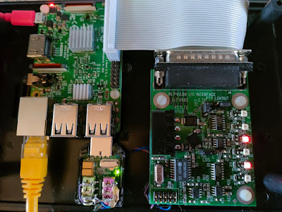
I have just completed the install/build/modification of an SVXLink Server on a Raspberry Pi 3 b connected to a modified IRLP Board which is then connected to a amateur radio VHF Transceiver.  Lets take a closer look at the main "ingredients" of this  project.

Overview of the Project:

What is an SVXLink Server? The SvxLink Server is a general purpose voice services system, which when connected to a transceiver, can act as both an advanced repeater system and can also operate on a simplex channel. One could call it a radio operating system.  SvxLink is very extensible and modular. Voice services are implemented as modules which are isolated from each other. Modules can be implemented in either C++ or TCL.

Examples of modules are:

    Help  — A help system

    Parrot  — Play back everything that is received

    EchoLink  — Connect to other EchoLink stations

    DtmfRepeater  — Repeater received DTMF digits

    TclVoiceMail  — Send voice mail to other local users

    PropagationMonitor — Announce propagation warnings from dxmaps.com

    SelCall  — Send selective calling sequences by entering DTMF codes

    MetarInformation  — Play airport weather information

    Frn  — Connect to Free Radio Network (FRN) servers

What is a Raspberry Pi 3 b? The Raspberry Pi 3 b is a low cost high performance single-board computer. The Raspberry Pi was developed in the UK by the Raspberry Pi Foundation. The Raspberry Pi Foundation's goal is to "advance the education of adults and children, particularly in the field of computers, computer science and related subjects." Many people have used Raspberry Pi’s to make things like cameras, video game consoles, robots, web servers and media centres.

What is IRLP (Internet Radio Linking Project) about? The aim of this project is to reliably and inexpensively link amateur radio systems without the use of RF links, leased lines, or satellites. The IRLP uses Voice-Over-IP (VoIP) custom software and hardware. Coupled with the power of the Internet, IRLP will link your repeater site or simplex station to the world in a simple and cost effective way. IRLP operates a worldwide network.

What is AllStar? AllStarLink is a world wide network of Amateur Radio repeaters, remote base stations, and hot spots accessible to each other via the Internet and/or private IP networks. AllStar software runs on a dedicated Linux computer (including the Raspberry Pi) that you host at your home, radio site, clubhouse, school, university, workplace, or computer center. AllStar is based on the open source Asterisk PBX and is released under the GNU GPL and is free for anyone to use. The core of AllStar and AllStarLink is the powerful app_rpt application and associated modules that load into the Asterisk PBX system.

As can be seen from the above each one of the building blocks are fairly complex and powerful tools that can be used by radio amateurs.  In this post I will skip AllStar and will later provide info in a future posting.  Lookout for the posting!

Background of this Project:

My first VOIP AllStar Node was build way back then and it consisted mainly of a Raspberry Pi 3 b, Hamvoip AllStar Software, modified USB Soundcard Dongle and a UHF Handheld Radio.  I modified the USB Soundcard Dongle to obtain PTT and COS from the onboard chip.  I stuffed up 2 dongles and was successful with the third board.  See my eyesight is bad and this resulted in bridges on the surface mount chip.  Be as it may the node is still running and used as the GRHub Network Node.

After establishing the GRHub Network in Mossel Bay it soon became apparent that we need a few more nodes in this area.  I did not look forward to modify another USB Soundcard Dongle or to import ready made URI (USB Radio Interface) or any of the other boards as our currency would push cost through the ceiling.  I looked at several alternative options relating to the USB Radio Interface Boards/Units.

Now this is where I ran into IRLP. (Internet Radio Linking Project)   I considered obtaining an  IRLP setup locally as I knew there was a few IRLP nodes up and running in the past.  I would run an  IRLP node and link that to the existing GRHub Network Node.  However I had one big problem!  IRLP is not opensource and is not compatible with other networks.  This would mean that I will have to go through a registration process to obtain all the necessary "goodies", pay the prescribed fee which once again would push the cost up due to the Rand / Dollar currency exchange.  Once again not a viable option.  Another hurtle was the fact that IRLP can only support half-duplex audio.

During my browsing of the Internet regarding IRLP I looked at the PCB interface closely and noticed that it still uses a 25 pin parallel connector (no problem) however my eye noticed that provision has been made for several indicating LED's example, COS, PTT, DTMF, AUX1, AUX2, AUX3. This raised the question why can this PCB not be used as a radio interface for SVXLink,  Echolink or AllStar or for that matter any other radio interface module.

I started to gather more information.  Remember IRLP was used on a way-back Desktop Computer.  I did not want to go that route.  My thought was to use a Raspberry Pi with SVXLink installed, attach a Syba USB Sound Card and connect the computer and the sound card to the IRLP PCB and finally to the Radio.  But will this work?  Well I had to give it a try!  I obtained two of the IRLP boards after advertising on the Pretoria Amateur Radio Swop Shop page.  This was risky as if it does not work then I can throw the boards in the Junkbox to be used as spare parts.

I looked for similar projects but could not find any concrete information.  I would have to rely on the bits and pieces I gathered from the IRLP, Raspberry Pi and SVXLink sites.  I found enough info regarding the IRLP  Project that enabled me to use the interface with the Raspberry Pi but no info on using the IRLP board with other software for which it was never intended.  I was determined to get this project to work.  The end result it is working great.  I received several reports that the node sounds great.  Of great benefit is the fact that SVXLink gives me several choices as mentioned supra.  

I am not going to go into much detail here as this will lead to a very large posting.   Ok lets start with all the parts you going to need:

Parts List:

     Raspberry Pi 3 b
     5v Power Supply Module
     5v Buck Converter Power Module
     Power Socket
     Modified Power Cable (USB)
     On/Off Switch
     Fuse Holder
     Ethernet Extension Cable
     9 Pin Ribbed Serial Cable (Comes with IRLP Kit)
      25 Pin Modified GPIO Cable (Make Up)
      Syba CM119 Soundcard Dongle
      7 Leds (Green, Blue, Red, Yellow)
      7 x 330 Ohm 1/4 watt Resistors
      Scrap copper connecting wire
      7 x LED Holders
      Cabinet
      Red and Black Twin Flex Wire + odds and sodds


Construction/Modification:

As stated before I will not go into detail here but I will however provide you with all the links and some images how to construct and modify this great working node.

IRLP Information:  Manual  +  Images GPIO Cable, Board Mods and Complete Setup

Syba Sound Card Modifications:  Start the conversion by carefully opening the device.   Be careful that you don't cut yourself or run a jeweler's screwdriver through your hand.   This process is much like opening a clam shell - using a pocket knife or small screwdriver with caution.   It might be helpful to grasp one half of the case in a small vice.   Also, be careful not to ram the knife or whatever into the interior of the unit, otherwise damage to the PC board or components can result.

Remove the bias resistor R6 on the CM119 side of the board.   This chip resistor, marked R6 - 1.2k ohm [122], normally supplies voltage to the electret condenser microphone.   These microphones have an internal audio amplifier which requires voltage to operate.   The removal of this resistor does two things: First, it removes the voltage on this lead eliminating the need for another coupling capacitor.   Secondly, it raises the input impedance from 1.2k to the value of the input control potentiometer - 100k ohms.   See the photo below for a detail of the location of this resistor.   

On the Microphone input we need to add a 1K resistor in series to reduce the gain.  There is also a Bias voltage on the mic input so the 1K also protects the radio from this voltage, and in some cases a capacitor will be needed to block the DC voltage. 

How to install/setup:

    1. Raspberry PI OS – Bullseye
    2. SVXLink
    3. USB Sound Card
    4. Alsamixer
    5. GPIO
    6. Radio Interface

Click HERE

Connecting LED'S from the IRLP LED'S to the front panel LED'S on the cabinet:   Connections are also made from the 5v Power Module that powers the Raspberry Pi to the Buck Converter which has been turned down to provide 3.3v to the front panel LED's and for the power LED.  The connection for the power LED comes from the 5v Power Module.  Front panel LED'S (COS, PTT, DTMF, AUX1, AUX2 and AUX3) are pulled down by Pi and IRLP boards through 330 ohm resistors.  The positive side of the LED's goes to 3.3 volts from the Buck Converter.  The power LED indicator is fed from the 5v supply through a 330 ohm resistor.  See the photo below for a hand drawn diagram.

Connecting the node to an amateur radio transceiver:  Refer to the IRLP Information Manual above and also to your Radio's Owners Manual to make the necessary connections.  You will need to make up a cable for this purpose as radio connections differ from radio to radio. 

This new node is as far as I know the first VOIP node in South Africa that uses a modified IRLP interface board that dates back to the 1990's.  Yep you read correctly.  VOIP and IRLP was invented in the late 1990's as a way to connect/link repeaters, simplex links using the Internet,  there are still older equipment that can be used to provide far better performance than new equipment. 

The new node was tested over the past few weeks to ensure that all the current functions work as expected.  Curtis ZS6CMO obliged and connected to the new node.  We did a quick connect and audio  test which was successful.  I would like to thank Curtis for assisting me with the tests.  I decided to connect the new node to the UK Hubnet to see if there is any "fish out there".  Low and behold it was not long before Andy VK6KQ (Australia) called and Marko ZS1NEU returned his call via RF on 2 Meters FM.  The two of them had a great QSO and was later joined by John VK6LWB  (Australia)  and Andrew 2W0INY (UK).  Marko was mobile and I was stationary mobile with only a 2m handheld on hand.  In my opinion the audio quality and reception was just as good as the ZS1I-L  AllStar Node that is currently the main node in operation.

Thus far I am quite impressed with the functionality of the new node.  The node is still in a test phase and I will provide full details in a future post in this regard.  The hardware setup of the node is now completed however I will still play around with the setup of the software.  I have not tested the node with AllStar software but will do so in due coarse.  Hopefully I will be able to burn a new SD Card with the AllStar software on it, make a few changes and run AllStar from this node.  AllStar is after all capable of much better audio quality.  I will provide my findings running AllStar on this node in a future posting.

I would like to invite radio amateurs to use the node when it is reflected in Echolink.  It will be weekdays on test between 09h00 - 16h00 SAST.

The node particulars are:

  • ZS1I-R GRHub Network, MSB, ZA
  • Node Number:  929614
  • Connect via Echolink or RF 145.550 Mhz  88.5 hz CTCSS
  • This node will be  connected to the GRHub AllStar Network
  • The node timeout after 5 minutes if there is no activity and you need to reconnect.
  • Currently only one station can connect at a time.  This will be changed in future.
  • Further modules with great functionality will be added in future.  One such future is the ability to leave and audio message via the QSO Recorder on the mailing list.

What will the new node be used for?  Well that is an open question that I cannot answer at this stage but I can assure you that this node will be the "heartbeat" of the GRHub Network. I am also working on another experimental VOIP node that will if successful be easy and cheap to build.  I envisage that this node concept will allow fellow radio amateurs to obtain their own node to be used in the shack, mobile or portable.  Lookout for this node.

Finally I would like to thank the following radio amateurs for their support and willingness to assist me in testing this project.  Although I only mentioned a few here you are most welcome to join in on the fun:

Curtis ZS6CMO,  Thys ZS1TBP,  Marko ZS1NEU, Andy VK6KQ, John VK6LWB and Andrew 2W0INY.

Images and Video:  (Click on images for larger view.)


Video Clip:  (I apologize for the quality of the video as I did not have enough hands or a decent camera.)


Tuesday, December 20, 2022

Protect those expensive Shack, Repeater, Link, Node etc. batteries from early "Death"!!

During the "Lippeklap" Net held on 11 December 2022 we discussed the different type of batteries available on the market today to be used in Amateur Radio and you home.  This ended up in a very interesting discussion and several great ideas and information "surfaced" during the discussion.  Many participants agreed that batteries are the most expensive and important energy component used in the Shack, repeater site etc.  We all agree that your batteries need to be protected from under and over voltage to mention only two aspects amongst others.

Koos ZS5KDK and yours truly suggested that one of the following two battery protectors might be of use to radio amateurs as well as private individuals to protect those valuable batteries.  

Here are two battery protectors that are currently used by ZS5KDK and ZS1I:


The above BatteryMate protector is successfully used by Koos ZS5KDK on the Pietermartizburg Repeater Network.  Several models are available.

More information on this product can be downloaded   HERE  (PDF)


The above Victron Smart Battery Protector is successfully used by Johan ZS1I on the GRHub Network. Several models are available.

More information on this product can be downloaded HERE (PDF)

Finally:  With the cost of batteries today it is important to protect those batteries all the time.  Installing this unit will contribute to the life expectancy of your battery(s) in the Shack, Repeaters etc.  However a good solar controller and intelligent battery charger is a must if you want to extend and maintain the life expectancy of your battery(s).

Ed.  Many thanks to Koos ZS5KDK for sharing the information of the BatteryMate with fellow radio amateurs on the "Lippeklap Net'  that takes place every Sunday afternoon at 15h00 on Echolink ZS1I-L, AllStar Node 49355 and 145.500 Mhz Simplex  88.5 CTCSS Tone in the Mossel Bay area.

Monday, December 19, 2022

Installation guideline for Sun Geyser by Heinrich du Plooy

GENERAL WARNING: Never undertake a DIY electrical task or any other modification to you home if your home is insured. Always contact your insurance company and discuss your undertaking with the company. If you do not you will find out the hard way that the company will not cover you house or property if a disaster of some kind occurs. Ensure that you obtain the necessary permission and any certificates required. You have been warned!!

The installation must preferably be done by a qualified electrician and plumber.

The instructions below are a guideline for the modification of any geyser fitted in a house that has
approximately the same weather conditions as Pretoria, South Africa.

The warm water will smell like the PVC pipe for the first month, therefore when you prepare food
rather fill the pot with water from the cold water tap.


1. Fit the circulation pump close to the geyser.
2. Coil the PVC pipe; 100m for a 100-liter and 200m for a 200-liter geyser; and join it parallel
to the geyser, ensure that the flow direction of the pump and valve are aligned so that the water is
drawn from the cold/inlet side of the geyser. (There must be a master flow valve before the geyser
and a safety valve installed on the geyser for the pressure.)
3. Assemble the electrical circuit as in the circuit diagram; the supply voltage is obtained from
the isolator switch before the geyser element.
4. The timer settings:
a. Summer: From 09h00 to 15h30 the timer must activate the circuit for approximately
eight (8) minutes, every hour to circulate the water. (The length of the PVC pipe will
determine the switching time.)
b. Winter: From 12h00 to 15h00 the water can be circulated two (2) or three (3) times,
where after the element of the geyser must be switched on to heat the water to the
desired temperature, this will save on electricity, because the Sun Geyser is assisting
the geyser element during the winter.
5. Selection between geyser element and Sun Geyser:
a. Manual selection: The circuit breakers, of the geyser element and circulation
system, cannot be switched on simultaneously; otherwise the PVC pipe will act as a
radiator, and cool down the water in your geyser. The daily temperature will
determine which circuit will be selected.
b. Automatic selection: The selection as (in paragraph 5.a) can be done
automatically, but will complicate this modification and make more expensive. It can
be done by installing a temperature sensing circuit on the neutral line of the geyser
element and the neutral to the relay of the timer circuit.
 

The total cost of components will be approximately
R2000 (Eskom account for the year 2012), the installation, if done
by an electrician and plumber, will cost extra.

(If you decide to use this concept please make a R100 donation
to the NG Kerk Concordia for each installation) 

The PDF file with larger image is available  HERE

Ed.  With Phase 6 Loadshedding now a regular occurrence in the country the above installation will surely save you money and also provide you with warm water whenever you need it, weather permitting of cause.  Thank you very much to Heinrich du Plooy for making this guideline available.


Opbou na Son Energie en Onafhanklikheid deur Cristi Grobbelaar ZS4CGR

GENERAL WARNING: Never undertake a DIY electrical task or any other modification to you home if your home is insured. Always contact your insurance company and discuss your undertaking with the company. If you do not you will find out the hard way that the company will not cover you house or property if a disaster of some kind occurs. Ensure that you obtain the necessary permission and any certificates required. You have been warned!!

Foto hierbo - Slegs ter illustrasie.


ZS1I Opmerking:  Ons het gistermiddag 'n baie insiggewende en leersame "Lippeklap" Net op die GRHub Netwerk - ZS1I-L gehad.  Die onderwerp was:

"Hoe hanteer jy Phase 6 Beurtkrag in jou HOK en Woning? Voorsien jy dat beurtkrag gaan afneem of toeneem? Kom gesels lekker saam oor die twee vrae. Ek weet beurtkrag is al holrug gery maar dit beinvloed ons almal en glo ek dat ons kan leer by en van mekaar oor hoe om dit te hanteer en te versag of heeltemal te systap! Na afloop van Lippeklap sal ek die volgende PDF Artikel beskikbaar stel: Opbou na Son Energie en Onafhanklikheid - Saamgestel deur Christi Grobellar ZS4CGR. Baie dankie aan Christi vir die artikel en goeie raad!! 

Die "Lippeklap" Net het vir meer as twee ure geduur en nog was dit einde niet.  Daar is derhalwe besluit om die onderwerp in die toekoms verder te bespreek.  Moet nie die volgende "Lippeklap" Net misloop nie.

Baie dankie aan al die 19 stasies wat ingeskakel het.  'n Besondere dank aan die deelnemende stasies wat 'n waardevolle en leersame bydrae gelewer het.  Dit word opreg waardeer.

73

Johan ZS1I


Opbou na Son Energie en Onafhanklikheid deur Cristi Grobbelaar ZS4CGR 

PDF available:  HERE

My pad na son energie het in 2004 begin. Ons was van plan om op die banke van die Oranje Rivier bokant Aggenys ’n plaas te koop. Op die grond was nog nooit twee bakstene op mekaar nie. Kaal landelike grond, 6500Ha groot.

Ek het my eerste panele 2x70W gekoop teen R2500, drie tweedehandse 104Ah batterye en ’n 400W 'ou tipe' omsetter. Vir ’n jaar was dit ons enigste energie. Daarmee het ons een rekenaar kon bedryf vir maks. een uur per dag. Drie florescent 8W kar 'lead lights' was ons lig in die drie army tente wat ons 'huis' was. Stoof en karavaan vries kassie was op gas. Warm water uit die donkie was net wintertyd nodig. Terloops, somer temperature in die skaduwee het 48°C bereik en in die tente tot 57°C. So teen 3h soggens het die temperatuur onder 32° gedaal en kon ons gou bietjie slaap voor die son weer opkom.
Hierna het ek vir drie jaar in die landbou gewerk en toe stuk-stuk getrek na die familieplaas waar ons nou voltyds woon.

In 2006 het ek begin speel met alternatiewe warm water stelsels (wat ons nou nog gebruik). Swart PVC klas drie 25mm pyp, 200m lank, opgerol en bedek met tonnel plastiek (teen wind -wat so 4j hou- foto). Geen opgaar houer nie, die druk van die watertenk voer die pyp en ons moet sorg dat ons voor sononder klaar bad en stort. Dag temperatuur van die water is byna konstant op 75°C, heel bruikbaar, heeljaar deur, behalwe op swaar bewolkte dae (omtrent 7 dae per jaar), dan gebruik ons warm water uit ’n 50ℓ geysertjie wat van die sonstelsel af warm gemaak word. Ons het tans ook 'blou pype' vir die kombuis en veldstort. Warm water is hier volop.

Dit is die agtergrond.

Net eers hoe al my son panele werk. Ons panele is in 'bondeltjies' gebou oortyd, op ’n middel paal (pivot) sodat as die paneel regop staan die onderkant so 300mm van die grond af is. Hulle kan dus roteer. Dan kan die rame waarop hulle gebou is ook vertikaal gekantel word. As hierdie dubbel beweegbare metode gebruik word, lewer elke paneel tot 160% van ’n vas gemonteerde paneel se krag (dus eintlik ’n besparing is panele). Tans het ek agt individuele 'bondels'.
En ja ek verstel hulle met die hand omdat ek die tyd het en die oefening nodig het. As ons weggaan, draai ek hulle Noord tot ons terugkom. 

Hier is my huidige 8 + 3 bondels:
2x 70W 12V Voer lood-suur batterye vir radio’s en ander 12V toerusting
2x 80W 12V Voer LiPO batterye en 5kW omsetter
6x 80W 12V Voer LiPO batterye en 5kW omsetter
2x 325W 24V Voer LiPO batterye en 5kW omsetter
4x 180W 12V Voer LiPO batterye en 5kW omsetter
2x 170W 12V Voer lood-suur batterye vir radio’s en ander 12V toerusting
1x 335W 24V Op karavaan dak foto
1x 225W 24V Op bakkie 'canopy'
1x 170W 12V Op bakkie 'canopy'

Hierdie 'bondels' was een-een aangeskaf, nie alles gelyk nie. Op die oomblik is die maks. lewering so 2.2kW.  Ek het baie lank gewerk met ’n motor battery bank van tot 15 batterye. So 3 jaar terug het ek ’n ou lood-suur 48V stelsel geskenk gekry, maar die 2V selle (24 selle) het nie ’n jaar gehou nie, waarna ek besluit het om oor te gaan op LiPO batterye. Omdat ek nie die LiPO batterye geken het nie, was ek geadviseer om 2x 3.7kW batterye te installeer, maar toe ek gaan sit en my somme maak, het ek die verskaffer gekontak en dit vermeerder na vier. En net ’n maand later het ek nog twee by gekoop, dus ses batterye van 3.7kW. Totaal nou 22kW. Terloops, 2.2kW bron vir 22kW batterye? Dit werk,
so 3½ uur se vol son en my laaier skakel af, alles is vol. En in bewolkte weer hou alles so drie dae voordat ek die Lister se hulp moet inroep.

Nou hier kom ’n interessante punt. Ek het gou agtergekom dat ek steeds nie genoeg rugsteun krag het na my sin nie, maar nog twee batterye sou meer as R30k kos, wat ek nie wou uitgee nie. Lank geloop en dink. Sien, ek het ’n gas yskas wat teen 300W konstant loop (die koste van gas was ’n groot deel van die motivering om oor te gaan op LiPO). Dit beteken 19kg gas per maand teen ongeveer R500/m. Maar die ou yskas kom al amper 15j saam met my en werk goed. Na heelwat dink het ek besef dat die uitweg was om die yskas te vervang i.p.v. batterye te koop. Die nuwe yskas gebruik net 80W en is nie konstant aan nie. Dit het 'veroorsaak' dat ek ook ’n kas vrieskas by gekoop het wat ook net 80W benodig. Die twee saam het minder as een battery gekos en verder nog R500/m se gas bespaar. ’n Goeie kompromie en my krag benodig het omtrent halveer.

Al ons gedagtes moet die volgende patroon volg: as jy nie jou inkomste kan vermeerder nie moet jy jou uitgawes verminder en as ek om my rondkyk, sny sal ons moet SNY.
Vir ’n stoof gebruik ons meestal ’n twee plaat stofie, ’n Elektriese plastiese ketel gebruik minder energie as ’n glas/metaal ketel omdat ek nie die glas/metaal hoef te verhit nie.
En hier is ’n wenner. Koop vit jou LV ’n nuwe druk-kook-pot die elektroniese soort. Hoekom? Want hy werk op 2bar druk (i.v.m. die oues wat op 1.2bar werk), maak taai vleis binne minute sag en gaar en gebruik baie minder krag en tyd as enige ander metode. Voordeel? Die LV 'smile'. Wat wil ’n LV hê? Warm water in die badkamer (en kombuis) en ’n gerieflike kombuis (en baie tyd vir haarself).

Nou kom ons by beligting.
Op Swartbas (plaas) het on 'lead lights' gebruik teen 8W elk.
Op Klein Kortlaagte (plaas) kon ons nie die 'luxury' bekostig nie. (tussen die twee het ek al my kapitaal 'verloor' deur 'diefstal'). Hier, het ek begin met een loodsuur battery (hier is ’n Lister, maar diesel kos geld) en kon dus nie die gewone ligte aandryf nie. Ek het ligte 'gemaak', ek het plastiese versierings-balle met fasette gekoop (O.D. 30mm), ’n gaatjie in geboor en ’n wit LED daarin monteer, drie in ’n ry met ’n weerstand vir stroom beheer en siedaar, hy werk van 12V af en gebruik 20mA. Gou was die hele huis 'belig'. Toe die 'strip LEDs' op die mark kom (of het ek dit ontdek?), het ek sistematies al die ou LED-balle vervang. Teen 50mA per lig. Ons het lank so gewerk, ons kon alles sien en doen wat nodig was. Laas jaar het ek op ’n verbetering afgekom. ’n Vriend wou sy neon lig vervanging (LED strip) waarvan die glas gebreek het weggooi, gou het ek hom oortuig om dit vir my te gee. By die huis het ek die krok met 'cable ties' op ’n 'dowel rod' vasgetrek nadat ek dit getoets het en hy werk nou nog in ons werkkamer (18W). Dit het my weer op ’n ander idee gebring. Ek het vir my van die neon vervangings buise (8W) gaan koop, ou geblaasde lampe se bajonet stert afgehaal en bedraad op die LED buis. Nou hang hulle vertikaal in die plek van gewone lamp aanhegtings en dit werk goed.

Nou-ja, dit alles kom oor die verloop van 18 jaar, sien, dis nie nodig om ’n hoop geld op een slag uit te gee nie, maar maak net ’n begin, dit sal self  kleintjies kry (nes radio’s en antennas, Hi! 


Groete

Christie Grobbelaar ZS4CGR

Friday, December 16, 2022

2007 ZS1I UHF 10mW Tracking Transmitter Project.


  (A 2007 ZS1I EXPERIMENTAL RESEARCH AND DEVELOPMENT PROJECT)

NOTE:  This 2007 ZS1I project is not an ARDF (Fox Hunting) transmitter.  However it can easily be modified to be used as a very interesting fox.  All you need to do is to remove the TX unit and replace it with a 2m HT.  You can then use the correct fox hunting frequencies.  This was one of the most enjoyable projects I ever constructed.  Great fun and interesting to see how far 10mW can get you on UHF.

I always had this crazy idea of in sending “something” up in the sky with an amateur radio payload on board. I had a look at several helium balloon and rocket projects but due to various Governmental and Aviation “red tape” in this country, I decided the next best option for the time being would be to use a kite to carry the payload. You might say what a waste of time but did you know that a World Kite Altitude Record of 14,509Ft (4422 meters) was set by Richard Synergy in Kincardine, Ontario, August 12, 2000 for a single kite. Needless to say I am not currently interest to better the record. I am more interested in constructing a useful and simple amateur radio payload that can be built and used by fellow radio amateurs in model rockets, model aircraft, balloon flights, kite flights, foxhunting, tracking animals and even tracking whatever needs to be tracked.

OVERVIEW:

There are many problems to overcome when designing an amateur radio payload. The main “obstacles” being size, weight, expense and versatility. Size and weight are obvious problems although not such a big problem as some kites can carry several grams if not up to half a kilogram, but the lighter the payload the better. Also important is the expense. Like it or not I alone carry the budget and flights can go wrong, horribly wrong. Versatility in the field is another prime consideration, including consideration of multiple sensor configurations (both analog and digital), and compatibility with standard receivers, antennas and transmission modes. Having said that, I decided to start small and then add-on as the project develops. What started off as a payload for a kite suddenly changes to a tracking transmitter or some kind of ARDF. I envisage that the payload will be constructed in several stages:

Stage 1: UHF Tracking Transmitter.

Stage 2: APRS Module and Transmitter

Stage 3: Simplex Repeater

Stage 4: Cross Band Repeater

Stage 5: Meteorological Sensor Board

Stage 6: Who knows? Imagination is the key to several more stages

What started off as a payload for a kite suddenly changes to a stationary tracking transmitter. Be as it may it gave us great pleasure and insight into UHF low power (QRPP) operation and will the experience gained be used to complete the Kite Payload at a later stage. (Below: Picture of the UHF Tracking Transmitter.)


The “brain-module” (PIC Microprocessor) was designed to send morse code telemetry to a FM transmitter and then into a 50-ohm antenna load. The “brain” consists of a PIC12F675 flash micro controller. The “brain-module” PCB also accommodates a 3 volt battery power source, two resistors, J- Adapters, link, IC Socket and other connector blocks.

The 433 Mhz transmitter is tone modulated by the microprocessor approximately every two seconds. A Morse code call sign ID (ZS1I) is transmitted approximately every 30 seconds. The microprocessor generates “beep” tones approximately every 1 to 2 seconds and a call sign ID every 16 “beeps”. A piezo buzzer can be used to produce sound from pin 5 of the PIC. This is useful if you want to have an outside audible tone in locating the payload after flight.

Space does not permit me to explain the PIC12F675 chip operation and programming to the full. Please note I did not write the ASM file for the PIC, as I did not deem it necessary to “re-invent the wheel” again. Recognition will be given to the appropriate developers and sources at the end of this article.

I chose a 433 Mhz transmitter to avoid “clashing” of transmitters at a later stage.


 Technical Features of the Transmitter:

· SAW resonator stability

· Carrier frequency: 433.75 Mhz but adjustable

· Supply: 12 Volts

· 15 mA consumption with TX enabled

· RF output impedance: 50 Ohm

· Output power: 10mW (Hey, QRPP here we come!)

· Dimensions: 40.6 x 19 x 3.5 mm

· Construction: Surface Mount Components.

Interfacing the transmitter is simple. Finally the antenna is the single most important item that will determine the range and audio quality of the project. Imagination and exploration is the key elements here. The test quarter wave antenna (16,4cm) I used is made from brazing rod and is connected directly to the transmitter with a short piece of RG174 coax cable. My homebrew 4-element 70 cm Yagi antenna gives the gain I need for longer distances, but will be very difficult to use in flight. A simple wire antenna work well (range restricted) and can be coiled to save space.

CONSTRUCTION:

The “brain-module” is constructed on a standard size single-sided printed circuit board.  The PIC is inserted in a 8 Pin IC Socket and the rest of the brain- module components are directly installed onto the PCB.  Soldering is straight forward and to the point. Keep the power leads as short as possible.

The FM audio transmitter is a ready to install module with a LF section and Modulator.  Two AC-coupled amplifiers with voltage gains of:  AMP 1 = 20 and AMP 2 = 5 and have a LF bandwidth of 20 Hz to 30 Khz. The FM modulator is an oscillator stabilized by means of a SAW resonator and modulated by a varicap diode.  In order to improve the signal-to-noise ratio and the dynamics of the demodulated signal it’s advisable to fit a pre-emphasis network between the 1st and 2nd LF amplifier stages.  The pre-emphasis network shown in the block diagram, lowers the bass tones by about 6 times with respect to the trebles, makes the FM modulation index approximately constant over all the audio bandwidth and increases the available dynamics for the bass tones. 


Pin 2 of the transmitter makes it possible to enable or disable the FM transmitter simply by interfacing it with TTL or CMOS logic families supplying output logic levels of 0 to 5V and 0 to 12V respectively.  I installed the transmitter module with the pre-emphasis network on a small piece of perfboard.  The few connections required are pretty simple and straightforward. Power to the transmitter is supplied by a small 12V alkaline battery, which is normally used in lighters, camera flashes and pagers.  Data is sent from the PIC into the transmitter at pin 4.
The single most important component that controls the system range and frequency is the antenna. Three antennas are described by the manufacturer of the transmitter module nl. Helical, Loop and Whip.  I used a whip for testing purposes with a length of 16.5 cm from antenna pin 2 and later successfully used a 4 element Yagi and a 8 element Quagi in field operation.

INITIAL TESTING:

Inspect all solder joints on the PCB and Perfboard for solder-bridges and bad joints.  Install the 3V Lithium battery for the PIC and then the small 12V battery for the transmitter.  Confirm operation of the transmitter.  If the transmitter function then it is ready for use.  I tested the transmitter on the workbench with the whip antenna.  This antenna yielded a ground-to-ground distance of well over 1000m.  But the big test was yet to come.

OPERATION AND TEST RESULTS:

A first “formal” testing schedule was held on Saturday 28 April 2007 as part of “Marcony Day” activities in the Southern Cape.  Francois ZS1Q contacted me early on Saturday morning to make final testing arrangements.  I could feel the excitement building while one question keeps coming up “Will 10mW RF power on FM (No line of sight) be enough over a distance of 45.5km of which 23.7 km runs over the ocean?”  Time will tell.  The first test was done on the workbench at the QTH of ZS1I with the whip antenna.  Batteries were installed and 145.550 Mhz Simplex was used to co-ordinate the 70cm FM QRPP tests between ZS1Q and ZS1I.  The transmitter was left standing upright on the workbench and ZS1Q was given the green light to monitor the 70 cm frequency for the QRPP FM signal.  After 15 minutes it was clear that no audible signal was heard and it was decided to get mobile to a high point and test again.  This time using two different antennas, the 16,5mm whip and a 4 element portable Yagi.  Yet no success over the distance and from the high point.  Enthusiasm soon turns to disappointment and on my return to the QTH it was decided to connect the fixed (No rotator) 8-element quagi antenna to the transmitter.  Yet again no success.  I then decided to leave the transmitter in the shack with the quagi antenna attached and to get mobile with the 4-element yagi and Yaesu FT817.  

The signal was clearly audible for up to a distance of 3.4 km where after I ran out of ground.  Alternatively I had the option to charter a boat to trace the signal over the ocean, which was impossible at such short notice.
The back to the shack option where chosen where a on air meeting was held to discuss the operations of the morning.  A unanimous decision was taken that despite the lack of success, this is definitely not the end of the road.  A decision was taken to evaluate all receiving and transmitting equipment before future tests are carried out.

TESTS: 1 MAY 2007:

Round about 07h30 after a cup or two coffee I received an SMS from Francois ZS1Q instructing me to switch the 70CM UHF TRACKING TRANSMITTER on around 08h00, as he was ready to hunt the 10mW FM signal.  His equipment consisted of a Yaesu FT857 and an 8-element 70CM Quagi antenna.  He decided to mobile towards the Outeniqua Mountains to an area where he thought would be the best to receive the signal.  We used 145.550 Mhz Simplex to keep in constant contact during the “searching” process.  Round about 8h12 ZS1Q contacted me to confirm his position.  After setting up his equipment he realized that there was an obstacle (mountain) between him and me and that this position would turn out to be unsuitable.  He did listen but receive no signal and decided to move to an area lower down the roadside.  ZS1Q stopped alongside the Outeniqua Pass, Blanco and George intersection. A few minutes later at 9h25 the audio of the tracking transmitter could be clearly heard on 145.550 Mhz.  Francois voice suddenly interrupted the audio with confirmation that he is receiving the signal. The air went silent for a couple of seconds and then we both realized that the 10mW signal was audible over a longer distance than before. A record distance of 41.6Km. (for now) Francois copied the signal (S4 to S9) with fading at times.

The location was fixed at 33.55.38S, 22.24.50E with a height of 362m above sea level.
The signal could be heard for several minutes and ZS1Q decided that with the good conditions at hand that he would like to move towards his QTH to investigate the possibility that he might hear the signal from his shack.  Francois and myself expressed great satisfaction with the distance achieved and it was clear that when conditions are favorable, a 10mW FM signal would be heard over long distances on the 70CM band. Unfortunately Francois could not hear the signal at his QTH but he is of the opinion that he will copy it in future. Congratulations Francois, you are the new Record Holder!!

Test results for 1 MAY 2007:

Establish a “one-way” contact on 70CM between Francois ZS1Q and Johan ZS1I with 10mW FM modulated signal over a distance of 41.6Km. (No line of sight)

ZS1Q POSITION:

Portable at George roadside crossing
33.55.38S, 22.24.50E, 362m above sea level
Receiving Radio:  Yaesu FT857
Antenna:  8 element 70cm Quagi (Horizontal polarized)
Distance from ZS1I:  41.6 Km
228 Degrees Celsius
ZS1I FIXED POSITION:

Mossel Bay KF15BT
34.11.54S, 22.06.10E
Transmitter: AUREL 70CM MODULE
Antenna:  8 element 70CM Quagi (Vertical polarized)
Output Power 10mW
FM Modulated
Distance from ZS1Q:  41.6 Km

WEATHER:

Misty conditions (Low level mist covering several hillsides and valleys) Francois ZS1Q indicated that he could not see Mossel Bay at all from his location. I am convinced that the weather played a big role in setting the distance of 41.6 Km. The conditions were as follow:

No Rain
Early morning dew.
Temp:  18 Degrees Celsius
Bar:  1016 Mb
Wind : None

The question that now comes to mind is:  “Will this distance be extended?  From those who participated a clear message:  “This is only the beginning!”  I have heard roamers of long antennas, pre-amps and “terrain searching”.  Bottom-line don’t miss the excitement if you live in the Southern Cape and who knows even up-country radio amateurs.  You never know what might happen.  Join in and have some fun.   Until next time.  Keep those soldering irons smoking!!


Above:  Inside view of the UHF Tracking Transmitter.  The PCB's are a real "Mixed Grill" variation....really ugly.


Above:  Picture of the signal received on the 28 May 2007 at 9h23 SAST.


Thursday, December 8, 2022

2m ARDF (Foxhunt) Transmitter Project - Eden Radio Club - ZS1ERZ


 I was recently approached by Corne ZS1COR to assist their club (Eden Radio Club ZS1ERZ) in obtaining 2 x ARDF transmitters to be used for "foxhunting".

I stopped some of my home brewing ventures as my eyesight took a turn for the worst and I had several  eye surgeries a few years ago.  Nowadays I concentrate more on doing home brewing projects using already build modules.  Be as it may I said to Corne that I still might have some foxes lying around somewhere in a junk box.  Well I found two of them with components but both were still in kit form.  I decided to give my soldering skills and bad eyesight a go in building these two transmitters.  I started with one but soon realized that it was a hopeless case.  Just look a the skew IC. This looks really bad!!!  I soldiered on but had no hope of getting the fox up and running.   Just look at the bad soldering.  During the process I bridged at least five tracks and components.  I finished the first fox and put it through the smoke test.   It passed!!  I was amazed that after all the bridges and bad soldering this fox was up and running.  The second fox is still in kit form.  I decided that this will be the very last home-brew kit project that I will undertake.  If the kit is not in a modular form then I will give it a pass.

The fox was send to Corne ZS1COR and I am sure we will soon receive further information on a foxhunting "DXpedition " in the George area.

The article and photos of the fox that I home brewed many years ago is available HERE. 

It was sold several years ago.

More information on the fox can be found HERE.

Photos:  (Click on images for larger view.)


Maintenance: Amateur Radio Mast at the Coast

  Over a period of time I noticed that one of my radio masts (Ex Wind Turbine Mast) was showing signs of rust where two pipes were welded to...