Showing posts with label Programming Radios. Show all posts

Wednesday, February 5, 2025

How to install CHIRP on Linux Mint 21.1 Vera


What is CHIRP?

CHIRP is a free, open-source tool for programming your radio. It supports a large number of manufacturers and models, as well as provides a way to interface with multiple data sources and formats.

In this article I will describe how to get the latest python3-based CHIRP-Next running on Linux Mint 21.1  Vera.

Before installing any packages ensure that your Linux Mint is fully updated and upgraded with the latest firmware packages.

1.  Install distro packages

Linux Mint

$ sudo apt install python3-wxgtk4.0 pipx (Enter)

2.  Once installed lets install CHIRP (and Python dependencies)

Download the chirp-20250110-py3-none-any.whl file located under the folder corresponding to the latest date.  (Note:  Latest date is - 20250131)  I downloaded the file to the Desktop of Linux Mint.  Easier to locate the file and work from the Desktop.  I later moved the file to the Downloads Folder once CHIRP was installed and running.

Before we going to install CHIRP one need to install the yattag package which was not installed in the latest versions of pipx.

I used the following command to install the yattag packages:

$ sudo apt install python3-yattag  (Enter)

The packages were installed without any errors.

Now lets install CHIRP

We need to be in the Desktop directory

$ cd /Desktop/  (Enter)

./Desktop$ sudo pipx install ./chirp-20250110-py3-none-any.whl (Enter)

CHIRP will now be installed without errors.   Where is it installed?  Go to Linux Mint files directory.  look for a folder .local and click on the folder.  You wil find a bin folder.  Click on bin and there is CHIRP.  Right click on chirp, click open and then on run and the program CHIRP will open in a new window.  You have successfully installed CHIRP.

But wait there are two "pop up" windows. Click OK and also OK for the CHIRP icon to appear in the Linux Mint Menu.  You can also add an icon to the desktop.  (Recommended)

Time to reboot your machine.  Once rebooted you can Start CHIRP via the Desktop Icon, Menu or the Terminal -  $ ~/.local/bin/chirp  (Enter)

Before you go ahead and program radios with CHIRP there is still two more "issues" that must be addressed for CHIRP to work 100%.

First we need to uninstall a utility program called:  BRLTTY  This program will prohibit you from accessing the COM port that CHIRP needs to talk to your radio.  Here is the command (still in he Desktop directory):

$ sudo apt remove brltty (Enter)

This command will remove BRLTTY from your computer.  The BRLTTY program is used by the blind and this program will hog your COM port.  CHIRP will not work.  Once the program is uninstalled you COM port will be available to use.

The second thing we need to do is to change the $USER that identifies the username of the individual running the command.

Find your username:  

$ whoami (Enter)

Your username will be displayed

Now enter the following command:

$ sudo usermod -a -G dialout [your username]  (Enter)

Your username will now be active when using CHIRP.

Time to Reboot your computer.  Once rebooted CHIRP will now be ready to program the listed radios using CHIRP.

REMEMBER to always make a backup file of your radios cps or code plug.  You never know when you going to need it if and when Murphy visit your Shack!

Have fun with CHIRP using Linux Mint 21.1 Vera!!


Saturday, February 5, 2022

Roll your own Pofung/Baofeng Radio Programming Cable.

John ZS1ZR:  Ek soek n Pofung/Baofeng prog. kabel te koop?

Image above: Lional ZS6DPL

Image above:  Michael ZS004 George

Image above:  Keverne ZS1ABU


Image above:  Those of you having an Arduino UNO available. Reset the Arduino chip with the yellow wire and use just the serial - USB chip on board. Cables made up with ordinary twin screened audio cable. - Danie ZS1DBJ  (Click on images for larger view.)


Comments Reboot Group:  2020/04/29, 8:02 am - Llewellyn Hewitt "ZS003" George: Die baofeng kabel werk met die pofung radiod 2020/04/29, 8:03 am - John ZS1ZR George: Reg so.dis hy 2020/04/29, 12:50 pm - John ZS1ZR George: Is hy te koop? 2020/04/29, 12:52 pm - Lionel ZS6DPL Pretoria: Nee maar sal na lockdown nog kan kry 2020/04/29, 2:29 pm - Keverne Thurling ZS1ABU George: I have 2 sets of these for those in my area. One set has adapters for most radios. Works well with Chirp. 2020/04/29, 3:07 pm - Johan ZS1I: Keverne John ZS1ZR and Francois ZS1Q might be interested. 2020/04/29, 3:38 pm - Keverne Thurling ZS1ABU George: Looks like the one for the Boafeng. I can let them loan it and return when finished. I have Chirp files with all repeaters and simplex channels, Also have Chirp Layout of you want to work AMASATs. 2020/04/29, 3:40 pm - Johan ZS6IW Dennotter: Is it possible to send the files to my email Any costs involved 73 2020/04/29, 3:40 pm - Johan ZS6IW Dennotter: Battle to get chirp working on win 10 2020/04/29, 3:42 pm - Keverne Thurling ZS1ABU George: Email is free, can I use the email on SARL. 2020/04/29, 3:46 pm - Johan ZS6IW Dennotter: Not member of Sarl zs6iw.Jw@gmail.com 2020/04/29, 3:46 pm - Keverne Thurling ZS1ABU George: I can't really comment on how to fix it, but the recomendations I have seen is don't use the drivers that comes with the interface, let windows detect and install. I have just been lucky in that the ones I have have always worked. 2020/04/29, 3:47 pm - ZS1CQ Corrie Kreef: Ek het a poking een maar kry hom nie om te werk met chirp .water dryer moet ek he 2020/04/29, 3:52 pm - Keverne Thurling ZS1ABU George: Done, Sent you a copy of my UV5R radios, 2020/04/29, 3:52 pm - Johan ZS6IW Dennotter: Thanks a million 2020/04/29, 3:58 pm - Keverne Thurling ZS1ABU George: I'm not sure if you have used chirp before, but you know not to use these files as is, its better to clone from your radio first, save a copy, then cut and paste the info from my file or just input the info by typing it in. In that why you retain all the settings info from your radio. Just a tip that you could already know. 2020/04/29, 4:08 pm - Johan ZS6IW Dennotter: both files r corrupt or only opens by the program but thanks any way not at home now to use program 2020/04/29, 4:32 pm - Keverne Thurling ZS1ABU George: Yes, if you try and open them by double clicking, it will give you an err as the file extention is .img. Windows sees it as a corrupt disk image file. You have to open it from within Chirp. 2020/04/29, 4:58 pm - Keverne Thurling ZS1ABU George: Corrie, Iike I said, I've not encounted a problem with the two I have. But from what I have read about others that have a problem with the driver, is that you should let Windows decide. But if the incorrrect one is already installed, you apparently uninstall the driver with the Universal Serial Bus controller removed, then plug in again. Mine has the FTDI CHIP and the standard Windows USB to Serial Bus controller driver works. See, if nothing goes wrong, you learned nothing. 2020/04/29, 6:01 pm - ZS1CQ Corrie Kreef: Running win7 maybe should use my win10 

Wednesday, February 2, 2022

Motorola GM300 remote hook switch modification for RX CTCSS

In a previous post available HERE I explained how to program RX CTCSS for the Motorola GM300 and M100.  In this post I will describe the modification I made to short pin 3 and 4 to make the radio believe that the microphone is on hook in the the mic-clip for RX CTCSS to work.

If you want to use the radio for AllStar or Echolink then before you program the CTCSS functions you need to note that the radio has a remote hook switch on the microphone that is used when the radio is in monitor mode.  The yellow monitor light on the front panel of the radio will be yellow and on under normal operation if programmed this way.  Once you programmed the radio for CTCSS this light will still be on and CTCSS will not function as it should.  The receiver will still open and allow any station in irrespective if CTCSS is programmed in the said radio.  If you programmed the radio for CTCSS and hook the microphone to a mic-clip the monitor light will go off and the CTCSS will function.  Unfortunately this will not work if you use the 8 pin microphone connector for AllStar or Echolink as the microphone will not be connected to the radio.  You need to short pins 3 and 4 on the RJ-45.  Pin 3 is the "hook" pin.  Pin 4 is ground.  By shorting pin 3 and 4 we make the radio believe that the microphone is on hook in the mic-clip for CTCSS to work.  The other option only works with the extended logic board radios.  You can program the accessory connector in wide mode function to use pin 7 and 14 (back of radio).  Once programmed you can jump pin 7 (ground) and pin 14 (Remote Hook Switch Input) that will do the same as shorting 3 and 4 on the RJ45.  In my case I cannot use the accessory connector as I do not have an extended logic board an therefor not the programming option in the RSS.  The only option left is to short pin 3 and 4 on the RJ45.  Please ensure that you use the correct pin outs.  I will not be held responsible if you use the wrong pins.  This will damage your radio!!!

Here is two images which is self explanatory:

The image above show the microphone and volume control board that must be unscrewed and disconnected from the logic board. To get to this board just unscrew the two hex bolts on the front panel of the radio.  Once open remove the J8 (blue) connectors from the logic board.  The head will now be loose form the body of the radio.  Now unscrew the two hex screws, one holding the wires that go to the logic board and the other holding the mic and volume control board.  Once done the board can be removed.


(Click on images for larger view.)

The image above show the microphone and volume control board removed from the radio header.  Turn the board upside down as showed in the images.  Now solder a bridge to the pins that are encircled in red.  I used a insulated piece of wire to prevent any short circuiting.  Once this is done you can assemble the radio and you hook switch modification is now complete.  Once power is connected the yellow monitor light will be off and RX CTCSS will work. If you press the monitor button on the radio the yellow monitor light will lite up and CTCSS will be overide.  Press the monitor button again and the light will go off and RX CTCSS is not active again.

Monday, January 31, 2022

GRHub 145.550 Mhz Simplex Radio now fitted with RX CTCSS (Continuous Tone Coded Squelch System)


Image: Comms Prepper

IMPORTANT NOTICE:  I have installed RX CTCSS on the ZS1I 145.550 Mhz Simplex Link Radio.  You will not be able to access the GRHub Network on 145.550 Mhz if you do not activate TX CTCSS on your radio.  The Receiver of the 145.550 Mhz will not open and your call will be ignored.  The CTCSS tone is 88.5 khz that you must program/set in your radio.  I advise radio amateurs to consult their radio users manual on how to activate TX CTCSS.  For those not familiar with CTSS, here is a short overview.

In short CTCSS (Continuous Tone Coded Squelch System) is used to accept desired signals and reject undesired signals on a radio channel/frequency.

"Different radio manufacturers give CTCSS different names. Motorola calls this feature PL or Private Line, Kenwood calls this feature QT or Quiet Tone, and GE/Ericsson/Harris calls this CG or Channel Guard. Radio Amateurs simply calls this feature CTCSS. However, no matter what name you give CTCSS, it still functions the same.

CTCSS employs sub-audible tones — which are below the normal 300 Hz to 3,000 Hz voice range of the radio — and uses 67 Hz to 254 Hz tone modulation placed upon the carrier with the voice traffic. These tones are selected from an industry-wide accepted list of tones (see below) and generally are available in your radio’s programming selection. The CTCSS function allows for encode and decode, whereby encode implies that a sub-audible tone is transmitted from the subscriber radio on the uplink and decode implies that a sub-audible tone is required to open the squelch on the subscriber radio receiver.

In amateur-radio, CTCSS encode is often referred to as “tone” in radio programming, while CTCSS decode is referred to as ”tone squelch.” In commercial radio programming, this same concept is referred to simply as PL, QT, CG (depending on the manufacturer) transmit and receive.

CTCSS is used to access repeaters and networks, allows multiple users to communicate on the same frequency (channel) without receiving radio traffic from each other, and is employed to improve radio operation in high RF noise, interference and congested areas. The operation of a receiver without CTCSS employed is known as “open carrier squelch” or simply “carrier squelch.” Operating a receiver in open-carrier mode allows the radio operator to monitor and receive any traffic on that particular channel. The Motorola radio I currently use on the GRHub Network has a Monitor feature which functions well.  All the handheld radios that I use also has this feature.

All conventional radio subscriber gear has a method for monitoring a given channel before transmitting. In generic terms this is called a “channel-monitor feature.” Manufacturers are required to have this feature in place on their subscriber products and radio operators are required to use this feature and monitor the channel before transmitting, to ensure that they are not interfering with another user operating on the same frequency.

Portable radios have a monitor button, typically on the side of the radio body, for the user to press and momentarily determine whether another user is present on the channel. Mobile radios also can employ a button on the front control panel for monitoring; however, monitoring a channel with a mobile radio can be accomplished with the removal of the microphone from the hanger, provided that the radio programming enables the function to operate. This microphone function ensures that the radio operator is not distracted from operating the motor vehicle while using the radio.

Some other methods employed to aid the radio user in monitoring the channel before transmitting include the programming of the radio’s LED indicators to illuminate while the channel is busy, even though audio is not heard from the speaker. Additionally, a channel-busy feature can be enabled during programming; this will inhibit the radio from transmitting until the channel is clear, which can be detrimental depending on how it is used. This feature is called “busy channel lockout.”

Finally:   If you experience any problems or need assistance please feel free to contact me or post your issues via Email by clicking HERE.  Even better join us on the AllStar/Echolink Network by connecting to ZS1I-L

Source:  urgentcomm.com

Thursday, January 27, 2022

How to Program CTCSS for the Motorola GM300 and M100 Radios


I have been playing around with CTSS (continuous tone-coded squelch system) programming the GM300 and M100 Radios to accept RX Squelch Code CTCSS.   There is also TX Squelch Code but for the purpose of this article I will not go into TX Squelch Code programming.  The service software manuals describe this proses in detail and can be consulted for more information.

What is CTCSS? Most two-way radios have 38 CTCSS codes which stands for Continuous Tone Coded Squelch System. Many two-way radio manufacturers have different names for this feature. These are some of the manufacturers and their names: Motorola: "Private Line (PL)," GE/Ericsson: "Channel Guard", E.F. Johnson: "Call Guard", RCA: "Quiet Channel", and some simply call it "tone squelch," " privacy codes," or "interference eliminator codes". The most proper name is CTCSS. These codes enable a two-way radio to keep the radio squelched (quiet) if the chosen code is not received with a transmission. In other words, the speaker of the intercom is not turned on even though a transmission is received. Technically speaking, a CTCSS tone code is a sub-audible tone/code which allows your radio to ignore (not hear) calls from other parties who are using the same channel. With CTCSS it may seem like you have your own private channel but other parties can still hear your calls if they set up their radio with the same tone code or no tone code at all. Both receiving and transmitting radios must be set to the same interference eliminator/CTCSS code or it will appear that a radio is not receiving transmissions. While CTCSS is said to transmit sub-audible tones (can't be heard on the radio's speaker), a radio is really continuously transmitting an audible tone below 300 Hz during a conversation. Each radio contains a filter to filter out anything below 300Hz so the tone is not heard even though it is there. Encoded tones are sent by the transmitter and decoded tones by the receiver to un-mute its speaker.

In short I want the receiver to unmute if a carrier with the specific sub-audible code (tone) is present.  This would come in useful in hopefully curb commercial break-thru by preventing opening the receive audio on both the above radios.  Now the programming of the radios is fairly strait forward but there are a few hurtles to overcome to get this to work properly.  I am not going to go into great detail here as the radio service software manuals contains all the necessary information except for the few important hints that I am going to post here that might be of help to others.

IMPORTANT HINTS:

1.  Establish the model and what type of Logic Board your radio has.  The two leading web-sites that has information on Logic Boards are listed HERE , HERE and HERE.  Please note that only the extended logic board gives you the option to program pin functions for the expanded 16 pin accessory connector at the back of the radio. 

2.  Please note that there is a difference between the GM300 8 channel radio and the 16 channel radio 16 pin accessory connector at the back of the radio.  Instructions for the Expanded Accessory Connector in the image below.


(Click on images for larger view.)

3.  The Motorola M100 Radius Radio only has a 5 pin accessory connector at the back of the radio which is not programmable.


4.  If you want to use the radio for AllStar or Echolink then before you program the CTCSS functions you need to note that the radio has a remote hook switch on the microphone that is used when the radio is in monitor mode.  The yellow monitor light on the front panel of the radio will be yellow and on under normal operation if programmed this way.  Once you programmed the radio for CTCSS this light will still be on and CTCSS will not function as it should.  The receiver will still open and allow any station in irrespective if CTCSS is programmed in the said radio.  If you programmed the radio for CTCSS and hook the microphone to a mic-clip the monitor light will go off and the CTCSS will function.  Unfortunately this will not work if you use the 8 pin microphone connector for AllStar or Echolink as the microphone will not be connected to the radio.  You need to short pins 3 and 4 on the RJ-45.  Pin 3 is the "hook" pin.  Pin 4 is ground.  By shorting pin 3 and 4 we make the radio believe that the microphone is on hook in the mic-clip for CTCSS to work.  The other option only works with the extended logic board radios.  You can program the accessory connector in wide mode function to use pin 7 and 14 (back of radio).  Once programmed you can jump pin 7 (ground) and pin 14 (Remote Hook Switch Input) that will do the same as shorting 3 and 4 on the RJ45.  In my case I cannot use the accessory connector as I do not have an extended logic board an therefor not the programming option in the RSS.  The only option left is to short pin 3 and 4 on the RJ45.  Please ensure that you use the correct pin outs.  I will not be held responsible if you use the wrong pins.  This will damage your radio!!!


I sure there are other hints for this, but the few listed above did the trick for me. 

You need to choose the RX squelch type that you will be using.  If no CTCSS then use CSQ.  I chose TPL as DPL and INV.DPL has certain limitation or hick-up which I am not going to go into here.  Google is your friend if you want to know more about DPL and INV.DPL


What is RX Squelch Code?

RSS LOCATION


DEFINITION 

Receiver unmutes if carrier with this specific sub-audible code is present. Receiver unmutes when it detects this code, allowing more users and privacy on a frequency. 

DEFAULT/CHOICES 
 
Default: BLANK 
 
Choices: (1) see TPL/DPL tables (Appendix C) or press F1 to display help.  If the Rx Squelch Type = TPL, then enter a frequency in hertz (Hz) or any code from Appendix C.  If Rx Squelch Type = DPL, type a 3-digit numeric code from the table in Appendix C.
 
DEPENDENCIES
 
Rx Squelch Type. 
 
EXCEPTIONS
 
If a Rx Squelch Type = Carrier Squelch, then squelch code is not available.
 
RECOMMENDATIONS 
 
Use when you want to have multiple groups using same frequency or when you want more privacy. Receiver response time of the PL detector can be improved slightly, for some codes, by de-tuning the PL code frequency by ±0.1 Hz. 
 
IMPORTANT NOTE 
 
TPL tones above 220 Hz will have more bleed-through to the speaker. DPL code 645 is a reserve code and will have a greater false opening probability. TPL codes near 120 Hz and 180 Hz have a high false opening probability due to 60 Hz AC power harmonies. Countries having 50 Hz AC power may have false opening on 100 Hz (code 1Z) and 150 Hz. TPL 134 Hz can be false-opened by DPL de-key.

Now onto  programming :

Programming the Rx Squelch Type

RSS LOCATION


DEFINITION 

Determines what form of continuous sub-audible code (along with carrier) is needed to open receive audio.

DEFAULT/CHOICES

Default: CSQ 

Choices: (1) CSQ  (2) TPL (3) DPL (4) INV.DPL
 
CSQ - Carrier Squelch. For receiver to unmute for all carriers. 
 
TPL -  Tone Private Line, CTCSS. If you want the receiver to unmute only specific carriers with specific codes, use TPL or DPL. For TPL you can type either the frequency in MHz or a 2-digit tone code (see Appen- dix C).
 
DPL - Digital Private Line, Digital CTCSSS. If you want the receiver to unmute only specific carriers with specific codes, use TPL or DPL. For DPL, enter a 3-digit tone code (see Appendix C).
 
INV.DPL -  Inverted DPL is only needed if a customer's system has an audio path “flipped”. 
 
DEPENDENCIES
 
Rx Squelch Type
 
RECOMMENDATIONS
 
Use when you want to have multiple groups using the same frequency or when you want more privacy. 
 
WARNINGS
 
 Do not use Inverted DPL (INV.DPL) for new systems! Inverted DPL is needed only for special applications, such as a “flipped” audio path or a multi-hop repeater. 
 
 
PROGRAMMING PROCEDURE 
 
1. Press F4 at the MAIN MENU to get to the CHANGE/VIEW CODEPLUG MENU.
 
2. At the CHANGE/VIEW CODEPLUG MENU, press F5 to get to the MODE CONFIGURATION screen.
 
3. At the MODE CONFIGURATION screen, select the mode number for which you want to pro- gram the desired Rx Squelch Type by pressing either the F3 or F4 keys until the desired mode # is displayed in the Name field.
 
4. Press Tab (or Enter or Return) until the Rx Squelch Type field is highlighted.
 
5. Use the ↑ ↓ arrow keys to select the desired Rx Squelch Type. 
 
6. To change the Rx Squelch Type on other modes, repeat steps 3-5. 
 
APPENDIX C:  


 Both radios were programmed with CTCSS in RX Squelch Code TPL.  Both were thoroughly tested and works great.  The GRHub Network Motorola Radio on 145.550 Mhz has been programmed for CTCSS but I have not yet activated it.  Once activated I will notify users of the CTCSS frequency which they will have to use to access the GRHub Network in future.
 
Another interesting feature to activate is Local/Distance programming.
 
Local/Distance
 
RSS LOCATION
 
 
DEFINITION
 
A feature that affects radio sensitivity and interference rejection. 
 
DEFAULT/CHOICES
 
Default: Local 
Choices: (1) Dx (2) Local
Local:  Use Local in areas of dense radio usage (suburbs and major cities). Local improves IM performance dramatically, but loses some sensitivity. 
Dx:   Use Dx (distance) when in an area where radio is decoding weak signals (rural area). 
 
RECOMMENDATIONS 
 
Use Local when in an area where there is a lot of interference (in the city). When frequently traveling between local and distant areas, use two channels with the same frequencies, only program one as Local and one as Dx. This way you can simply switch from the local channel to the distance channel as you travel from the city to a more rural area. Most control stations should be Local.

Finally: I trust that the above will be of help to other radio amateurs that would like to program Motorola Radios with the CTCSS code function.

Programming Example Images: 


Friday, December 31, 2021

#5 What is in the Box?

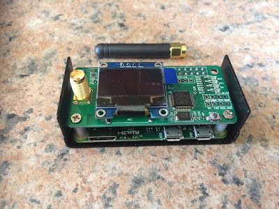
 Another What's in the Box, I hear you say Christmas has passed, so why this box?  Well it arrived late from overseas, but as they say rather late then never.  I received it on Wednesday and decided it was time to join the VHF/UHF digital radio side of Amateur Radio.  Yes it is a Hotspot and I will mainly use it for DMR. I am a newbie when it comes to DMR and will start from the bottom  and hopefully work my way to the top.  As far as I know there is no local radio amateurs playing with DMR so the Internet will be my Elmer.   The first step would be to get the Hotspot up and running and then program a new codeplug for my TYT MD380 HT radio.  Ya I want to start from scratch and learn all there is to learn.  No I do not want to just upload a codeplug and go the easy route.  So here is a few images of what I have been up to.  Update to follow once I get the Hotspot up and running.


Tuesday, November 9, 2021

To Split or not to Split…..Why do we have 600 khz Repeater Splits?


In the beginning of Ham FM radio involvement in the 1950s, the only equipment available was from manufacturers such as Bendix (yes, the brake people), Aerotron (yes, the same people who brought Gonset to Hams), Federal Signal (which made rail-road equipment), and others such as Link, Carphone, and RCA. You might also have heard of Motorola and General Electric.

The equipment was commercial and required conversion to Ham frequencies. Most radios were only wired for single-frequency operation. You might get a working radio for free, but two crystals were required for each frequency (transmit and receive) and they cost $5 to $15 each. By informal agreement, all two-meter rigs (that is, converted high band equipment) operated on 146.94 simplex. There were no repeaters at first. All communications was station to station. Rigs and antennas were optimized for that one frequency.

Eventually, repeaters were invented. Actually, they were put into use on Ham frequencies, just like they were for commercial users. Physics and experimentation showed that repeater receivers at sites where the transmitter and receiver were at the same location suffered less desensitization if the transmit and receive frequencies were far apart. Ham repeaters used various separations, but that meant a tuned antenna or tuned receiver front end had to be adjusted quite differently from the tuned antenna for a transmitter.

What to do to ensure peak performance? Practically, it was discovered that a split of 600 kHz was about as far apart as you could separate a transmitter and receiver in frequency to enable a single antenna tuning network to work well for both functions. Of course, the antenna would be tuned for a midpoint frequency, and that opened a bit more of the band for other repeater frequencies to be within tuning range.

But it wasn't always that way! The concept of 600 kHz splits was not intuitive. It required repeater owners be convinced they should conform to this radical idea. That is, repeater owners and operators had to be convinced they should spend money to buy more crystals and tune antennas just for conformity to a concept that meant nothing to them locally, especially when the repeater was coming in just fine, thank you.

Now, aside from the practicalities of allowing as many repeaters in the available frequency allocation, this was the tightest frequency split that would work. As repeaters' ranges extended, it became necessary for repeater users and owners to adopt a wider set of principles. (There were overlapping super-repeaters everywhere. You could use a walkie-talkie in down-town Boston and talk to Hams in Albany!)

The big picture became more important than local concerns and needs. A national norm was needed, developed, and adopted. That norm was 600 kHz. A practical, local example of cooperation: In New England, we had three major repeaters, each of which gave fine coverage that overlapped in Boston and its north-western suburbs.

The Concord, NH repeater had an output on 146.94 and an input of 146.31: a 31-94 repeater. Waltham, MA repeater's output was 146.64, input 146.34: it was set on 34-64. (It had less than a 600 kHz split because its receiver and transmitter antennas were separate and far apart.)

Mt. Greylock, in North Adams, MA output was 146.91, input 146.04: set for 04-91. As you see, none used 600 kHz splits. Each repeater trustee was reluctant to change because of their expense and the expense of their users to buy new crystals. But reason prevailed. One fateful day around 1973, the repeaters realigned to 600 kHz splits. Users in each area voluntarily swapped crystals (some met in parking lots to make the exchanges) and few met with any expense. Concord gave its 31 input to Graylock: Graylock was now 31-91. Waltham gave its 34 input to Concord; Concord was now 34-94. Graylock gave its 04 input to Waltham: Waltham was now 04-64.

Agreement and consistency!

Today, 600 kHz splits are the norm nationwide and that frequency split is pre-programmed in all our radios. Now you know why.


Eric Falkof, K1NUN

Monday, October 4, 2021

Re: The Garden Route Hub Network will be off line/air for maintenance and upgrade today.

 The GRHub Network is back online/on-air after several upgrades/updates and maintenance performed on the network.

As many of you might not know Linux is a great operating system but needs constant "fiddling" to keep it up to date and also to install new applications and futures.  It is not like Windows where you just click on a button and a few seconds later software is installed.  Be as it may I personally think that Linux is far better than Windows  ..... debatable ......yes.

Here is a list of upgrades that were done:

  • Installed a fan controller for the power supply of the Motorola Radio to keep it cool.   I need not switch the fan on manually anymore.
  • Upgrading Node 46765 firmware that enable me to automatically play any audio file or bulletins from a website or from a submitted file.  This entails the auto download of  say the ARRL bulletin and with a script I can now play the audio at a certain time and date without having to do anything on the node.
  • Cleanup of both nodes temp and permanent files/programs not in use anymore.
  • Modifying the electricity backup power supply for both nodes in the event that Eskom pulls a loadshedding stunt on us.  Installed a new battery backup.  The unit will now automatically switch over to battery power in the event of a power failure. 
  • Add a warning unit should the battery capacity fall below 11.1 volts.  The unit will sound an alarm and switch off after 2 min of warning time.  I am still not happy with this unit as I would like it to send telemetry/SMS to warn me should I be in town or mobile somewhere.  I am looking to replace this unit once I found a better unit.
  • I started working on another node to be a backup node should anything being done to the network.  This will result in no down time/off the air for upgrades of updates and maintenance.
  • Worked on the Connection Log files to differentiate between Internet and RF connections.  Due to local interference from time to time I can now easily establish the source and take the necessary actions if any.  I am strongly considering to install a cellphone auto cut-off board for the RF Link.  This will allow me to cut off the RF Link should the DTMF and Disconnect Function not function as a result of interference.  Watch this space.
  • Setup several monitor "stations" for nodes as well as the RF Link.  Auto audio recording of any activity on all nodes and the RF Link is now possible.
  • Compiled an activity/idea list for future enhancements.  A list of 10 ideas were jotted down.  These could be of interest to many.  More on this in a future post.
  • Worked on some backup instruction manuals/files  for AllStar, DMR, Linux and Radio Programming.  As we all know one cannot remember every piece of information or how to.
  • Finally:  A few odds and ends and before you know it, it was time to go to bed again.

I am happy with the upgrades.  Unfortunately there will be many more in future,  hopefully without the need of shutting down the network.

My apology for any inconvenience in this regard.

Wednesday, August 25, 2021

Programming old Motorola Radios ........ the "easy way".

Image: Repeater Builder.com

I played around this last few weeks experimenting with several ways to program old Motorola Radios. Not having any old and slow computers on hand I decided to look into programming these old work-horses with different OS, computers, etc. The Internet is packed with information but I guess 80% result in errors, faultfinding, bricked radios etc.

15 years ago I constructed my own RIB to program Motorola radios using old computers to successfully program these radios. I tried several other interfaces during last week eg. Real FT232RL-, CP2102-, Prolific PL2303 and a few homebrew programming cables. I used Windows7, Mint, Raspberry Pi 3, Raspberry Pi Desktop Debian 10 and WindowsXP. I ran into several brick walls which mainly include Com Port issues and reading issues of the radio codeplugs. In one instance the software gave me an OK test for communications but would not read the codeplug. I looked into using my homebrew RIB on a fairly modern hardware setup and using the original code to program the radios.

 I would however like to share a website which describes Programming Motorola Radios with a Raspberry Pi. Although this is not for the faint harted and only if you have knowledge of Raspberry Pi and AllStar software. I think this is a brilliant method. I ran into a few issues with the FTDI board being a cheap clone. The issue: It can only run 5 bits but I need 8. Here is the link if anyone on AllStar would like to try this method: https://hamvoip.org/hamradio/motorola_programming/ 

PLEASE: Do not ask me for the Motorola RSS Software. You can find it on the Internet.

I will provide bare skeleton information on how I program old Motorola Radios. 

Herewith the equipment that I use:

1. Laptop – Intel Celeron CPU 530 @ 1.73Ghz 1 Gig RAM. This laptop has no outboard serial ports. OS = Windows XP Pro.
2. Manhattan Laptop PCMCIA Serial Port Adapter. Model 176576 Chipset: 16C550 UART Port Specs: External DB9 port (RS232) Bus Specifications: Cardbus Type II , 32 bit, 33 Mhz, 3.3V card. Install driver as per supplied CD.
3. DIY RIB (Radio Programming Interface) as described by Colin (G1IVG) Link: http://www.g1ivg.com/motgm300.htm The Interface design has been tested on the following radio's: 3.1 GM300 (Connect to the Mic socket on the front panel of the GM300). 3.2 GM350 (Connect to the Mic socket on the front panel of the GM350). 3.3 M100 Radius. 3.4 GP300. 3.5 Maxtrac 840 - 800 MHz Trunking Radio. 3.6 Maxtrac 300, VHF 16 ch. 3.7.
4. 12v Battery for the RIB.
5. An old Motorola Radio as listed above.
6. DOSBox Software. Link: https://www.dosbox.com/download.php?main=1
7. Motorola DOS RSS Programming Firmware.

Setup:
1. First turn off your computer and any other connected peripheral devices. Insert the PC card into the PC card slot of your computer with the card’s 68-pin connector facing the slot. Make sure it is inserted properly for a solid connection. Turn the computer on. After boot-up install the Windows XP Driver for the Manhattan Laptop PCMCIA Serial Port Adapter.
At the Found New Hardware Wizard, select “Install from a list or specific location (Advanced)”; click “Next.” Insert the driver CD; check “Include this location in the search”; uncheck the other box; enter “D:\Cardbus\98XX\XP”; click “OK.” NOTE: Change “D:” if/as needed to match your CD-ROM designation. If the Hardware Installation window pops up, click “Continue Anyway”; click “Finish.” (The driver has been thoroughly tested for stability and compatibility.) Repeat steps 1-3 two more times. 5. Restart Windows to complete the installation.
2. Go to the Control Panel and then the device manager. 
3. Make note of what COM port was assigned to your adapter under “Ports” (COM1 in my case).
4. Right click on this and go to Properties.
5. Now click on the Port Settings tab and set the baud rate to 2400, and leave other settings as default. Click on Advanced. Enter. Remove tick in Use FIFO...... Ensure that Com Port Number is COM1 in the box below FIFO. Click OK and again OK. Close Device Manager. Now, Install DOSBox and let it install into its default directory.
6. Follow the DOSBox and Programming instructions as described in this link below and now Configure DOSBox to Run Motorola RSS.
7. Link: https://kk6jyt.com/motorola-radius-gm300-programming/ This website provide valuable information. Do not forget to read the comments section as well.

Using the above info, software and hardware I was able to program all my Motorola radios successfully!


Above:  Laptop fitted with PCMCIA Serial Port Adapter

 
Above: Homebrew Motorola Programmer

 
Above: Manhatten PCMCIA Serial Port Adapter 
 

Above: Card fitted to Laptop


Above: Top view of fitted card


Closure of this ZS Link Network Blog - 29 April 2026

This will be the final posting on the ZS Link Network Blog. This blog will no longer be updated but will remain available for research an...