Friday, December 31, 2021

#5 What is in the Box?

 Another What's in the Box, I hear you say Christmas has passed, so why this box?  Well it arrived late from overseas, but as they say rather late then never.  I received it on Wednesday and decided it was time to join the VHF/UHF digital radio side of Amateur Radio.  Yes it is a Hotspot and I will mainly use it for DMR. I am a newbie when it comes to DMR and will start from the bottom  and hopefully work my way to the top.  As far as I know there is no local radio amateurs playing with DMR so the Internet will be my Elmer.   The first step would be to get the Hotspot up and running and then program a new codeplug for my TYT MD380 HT radio.  Ya I want to start from scratch and learn all there is to learn.  No I do not want to just upload a codeplug and go the easy route.  So here is a few images of what I have been up to.  Update to follow once I get the Hotspot up and running.


Wednesday, December 29, 2021

Build this simple 2m VHF Yagi by ZS2U over the Festive Season!!


January 2008: I am always on the lookout to build a useful and practical VHF/UHF antenna. I ran into a very simple two meter beam as described in QSX the monthly newsletter of P.E.A.R.S. Al Akers ZS2U the author of the article is well known for his knowledge and enthusiasm around the developing and construction of antennas. I decided to build this antenna and give it a workout on VHF DX.

Al ZS2U write: "This antenna was developed for those amateurs who would like to have an antenna which performs somewhat better than a half wave dipole, especially for portable use, but do not wish to construct an elaborate multi-element beam with it's associated matching requirements and it's size and time consuming assembly of dismantling.

It is a two element beam, consisting of a driven element which is fed directly in the centre with a coaxial cable, and a reflector. The elements are made of 3 millimetre diameter brazing rods (one meter lengths). The boom is made of 20 millimetre diameter PVC electrical fittings and tubing, so make sure the fittings fit snugly onto the tubing. Dimensions are given in the diagram . The elements are mounted in the middle of one half of the couplings and this half is filled with epoxy resin or similar material to support the elements. Attach a piece of PVC tubing to the top of the mast to be used, and the T-piece is fitted onto this. The antenna itself takes less that a minute to assemble or dismantle. The driven element on it's own can be plugged onto the mast and used as a half wave dipole. Used this way, or as a beam, the measured SWR was 1,2:1 maximum across the two meter band. Gain is approximately 4 to 5 dB."


(Click on image for larger view.)

I decided to modify the antenna to suite my needs. I replaced the coupling on the feed line end with a PVC T-Piece which housed the two 475 mm driver elements. You will notice that the 20mm PVC fits snugly into the T-Piece. I inserted a short piece of PVC tubing on both ends of the T-Piece and cut them off flush with the T-Piece. Thereafter I fiited a wooden dowl into the 20 mm tubing. (See photograph for clarity.) I then drilled 3mm holes through the wooden dowls to fit the driven elements. This modification resulted in a very sturdy "element holder" to which I connected the RG58 cable. I assembled the beam and connected it to a SWR meter and two meter set. The SWR was reflected as 1.5:1. I was not very happy and decided to trim the driven elements. This resulted in a 1:1 SWR. 


My final measurements were:

Driven Elements: 460mm

Spacing between driven- and reflector element : 445mm

PVC tubing length: 170mm

Lenght of Coax::1100mm


It looked darn good and the SWR was "flat", but will this beam be any good. The first opportunity to test the beam was hampered by bad conditions although I managed to have a short QSO with Terry ZS2ABB in Port Elizabeth. A distance of over 300km. In the second attempt I worked Alex RW1ZC/MM on the 6/3/2008 on 2M Voice 144.400 Mhz Fm. Grid: KF35BP 368.3km. Made several contacts while mobile in Mossel Bay at different sites. Power 10 watts.

This proved that this little antenna is worthwhile constructing and is a real asset to my antenna arsenal. A bonus is that you can use this antenna either in the horizontal- or vertical polarized configuration.

So what are you waiting for get to your nearest hardware supply store and gather the necessary hardware to construct this antenna. You will be amazed at it's performance!!

Many thanks to Albert ZS2U for making this antenna project available for homebrew construction.


Photos:


Tuesday, December 28, 2021

Live Space Audio now directly available from time to time on the GRHub Network


Conversations between astronauts (some radio amateurs) aboard the International Space Station and Space Missions with flight controllers on the ground will be available live from time to time on the GRHub Network. The streaming audio of space-to-ground communications includes NASA/SPACEX commentary during specific space mission events and regularly scheduled space commentary will be relayed on the network.  The GRHub Network will also from time to time relay amateur radio contacts from and to the International Space Station as received directly on 145.800 Mhz FM.

The main object with these broadcasts :

  • Inspire an interest in science, technology, engineering and math (STEM) subjects and in STEM careers amongst young people and new radio radio amateurs;
  • Provide an educational opportunity for students, teachers, radio amateurs and the general public to learn about space exploration, space technologies and satellite communications;
  • Provide an educational opportunity for students, teachers and the general public to learn about wireless technology and radio science through Amateur Radio;
  • Provide an opportunity for Amateur Radio experimentation and evaluation of new technologies.

If possible radio amateurs are encouraged to relay these audio conversations on their local repeaters and on simplex. 

I will be using several hardware and software to relay the audio from several sources.  Please bear with me if there is a glitch or two in the beginning as this is also a learning curve for me.

Updates and Time Schedules of broadcasts will be available on the  GRHub Network Twitter Platform or on the far top right hand side of the GRHub Network listed as  Tweets by @HamRadioZS1I.


Images: NASA + ARISS

Sunday, December 26, 2021

DIY 12v - 48v DC Busbar Project for Solar Power Generator.

(Click on images for larger view.)

I am currently busy to build a Solar Power Generator to use in the Shack when Eskom starts with its loading escapades in 2022.  I will provide more information in a future post on the Solar Power Generator after completing the project. 

Now I needed a positive and negative 24v DC Busbar for all the relevant connections to be made instead of connecting it directly to the 24v battery bank.  Locally prices were so inflated that the cost of both the busbars would have been more than a thousand rand each.  I looked all over the Internet for good busbars at reasonable prices but the prices were far above what I consider as reasonable.  The alternative would be to roll my own positive and negative busbars.

I needed some good isolating material, a piece of copper bar and brass/copper bolts, washers and nuts.  I had a piece of 5mm Phenolic laminate that is used as isolation in large AC transformers. This material can withstand fairly high heat, not that I needed it as there are more than enough protection circuitry for all the equipment used.    The positive copper bars was salvaged from an old commercial welder that I stripped a few years back.  The brass bolts, washers and nuts I scrounged from my junk box although I had to purchase some as I did not have enough.

Building these busbars are easy.  The images below provides all the details.  All that now remain is to install the busbars to the Solar Power Generator platform.  Hopefully this will be done in the coming week.

Finally:  With a price range of R300 to over R1000 per busbar it is worthwhile to consider rolling your own.  Just ensure that the material you use is suitable to carry the volts and amps that you will be using.  I am considering to make two Perspex covers for the busbars.  This will only be done once the project is finalized.


Friday, December 24, 2021

UPDATE: IMET78754 Radiosonde observed on APRS-fi and tracked on the Internet.

(Click on images for larger view.)

Here are some more information that I gathered iro IMET78754.  First observed position (-33.97712, 18.59984 @ 212m 24 December 2021, T 11.42.28  000000Z by ZS1AEG.

The balloon burst at 22 380 meters altitude on the 24 December 2021 at 14h38 SAST.


IMET78754 Radiosonde observed on APRS-fi and tracked on the Internet.

(Click on images for larger view.)

I discovered  IMET78754 a Radiosonde on APRS-fi that was launched in Cape Town this afternoon.  My first observation of the balloon was at 14h54.  The relay station on APRS was ZS1SCI.  I tracked the balloon until 15h00 as this was the last transmission position by ZS1SCI.  At 14h54 the balloon moved in a Easterly direction at an altitude of 5944 m.  At 15h00 the balloon was still moving Easterly at 8 km/h and was 2033 m above ground.  I do not have any other information except for the info in the images below.  Maybe somebody can provide more information.  I wonder if it will be possible to track the Radiosonde in the Mossel Bay area?  Guess the only way to find out is to listen for the next Radiosonde launch....when??


#4 What is in the Box?


 I don't enjoy the commercial side of the Christmas Season, but what I do enjoy is receiving a present from dad to dad.  Old Father Christmas has arrived earlier this year albeit it being to dad from dad.  What is in the Box?  Well if you a radio amateur than it must be something to do with amateur radio.  No, it is not the latest high-tech HF radio from Icom, Kenwood or Yaesu.  Let's open the box (s) and see what is inside.


                            The one box contain a Motorola GM360 UHF Radio and accessories.

                                              But there are two boxes with the identical radios.


These two radios are in an excellent condition.  As already stated they are both UHF radios.  I will use both to enhance the GRHub Network in the new year.  

Finally:  To many this "What is in the Box?" is seen as bragging. Sure I will not be able to convince them it has nothing to do with bragging. It is called sharing projects and information when I use the equipment for the GRHub Network. I would like to appeal to other radio amateurs to send me images about their unboxing of amateur radio equipment that they bought or received.   Does not matter if it is a tiny piece of equipment or electronic parts.  Share your unboxing with us.  Photos and information can be send to the GRHub Network for publication by clicking HERE.

Enjoy your unboxing of amateur radio equipment this festive season!!

Thursday, December 23, 2021

UPDATE 2: VHF Low Loss Helical Band-Pass Filter Project for the 145 Mhz Band


Just a short real-time overview of the effectiveness of the VHF Low Loss Helical Band-Pass Filter for 145 Mhz.  To be short - this filter works as claimed by the Mile Kokotov Z33T.  Before connecting the filter I scanned the 2m band for local interference in the Mossel Bay area.  I was not surprised to receive interference/break through by commercial users in the amateur radio band while scanning the band without the filter for a lengthy period.  My station is close to a few commercial repeaters and telemetry transmitters. I ran the scan function with the filter connected to a VHF radio again for a lengthy period.  Both tests with and without the filter was recorded only when there was activity.  Well the final result is that this filter at my QTH resulted in a 99%  success rate.  The 1 % that caused the radio's squelch to open is attributed to the local authorities telemetry transmitters.  After a call to the local electricity department it was confirmed that they experienced problems and that it will be solved promptly by their service provider.  I can confirm that it has since been resolved.  Does this mean that I do not have any interference anymore.  No,  from time to time a get a carrier that opens the squelch on 145. 525 Mhz.  To solve this I will be adding CTCSS that will prevent the COS from being activated by this carrier.  An update on adding CTCSS to the GRHub Network 145.550 Mhz Link Radio will follow in the new year.

Finally:  A word of warning!!  There is high RF voltage present when transmitting and as stated by Mile RF voltages can be in the kV range.  This I can confirm.  When I transmit the top lid of the filter gets warm to hot.  So be carefull!! I am very happy with this build and the performance of the filter.  A added bonus is the 1:1 SWR with full 25 Watts output power.

Wednesday, December 22, 2021

Down Memory Lane: 2007 - 2008 K.C.A.R - Kite Carrying Amateur Radio Research Project (Part 2)

Aquilone 1 Payload Construction - 2008

The K.C.A.R Kite Project is well under way.  I am currently busy with the payload construction and hope to make the first payload test by the end of this week.  Here is a few images of the different electronic projects that will be installed in the payload bay.


GPS Antenna installed on PCB

GPS UBlox unit which will be connected to the Modified TinyTrak1 board for APRS tracking

Modified TinyTrak1 PCB which forms part of the APRS Tracker Unit

Meteo Board with Barometer, Hygrometer, Temperature meter and transmitter to transmit weather info to computer.

Transmitter for APRS Tracker unit.  The transmitter will transmit the exact location of the kite.

RS232 converter for converting GPS data.

The payload tray showing two compartments.  There will be 6 compartments in the final tray assembly.

The payload tray (Side view.)

The payload housing with two end caps.

The payload bay with two end caps (Side view.)

The payload bay and tray.


The payload bay and tray. (Side view.)

(Click on images for larger view.)

Assembly of the Aqualone 1 payload

Great news. I finished the assembly of the kite payload.  The "smoke test" on the K.C.A.R  Auqualone 1 Kite Payload was performed yesterday afternoon.  The result:  No smoke!  The payload performs well and final testing will be done later today.

I still need to build antennas for both the APRS Tracker and the WX Transmitter.  Photos of the payload will soon be published.  I am looking forward to the first flight of the K.C.A.R  Auqualone 1 Kite Payload.  All the transmitted data of the K.C.A.R  Auqualone 1 Kite Payload will be available on the Internet in real time format.  More information on this in future updates.

The Aquilone 1 Payload

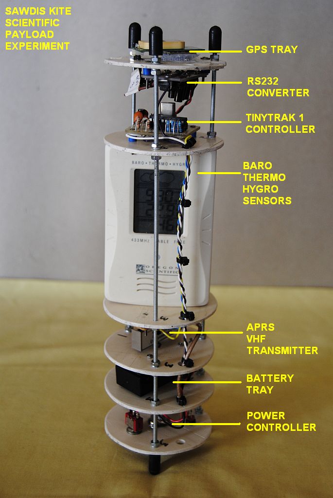
The K.C.A.R Scientific Kite Payload

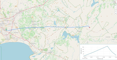
The payload is now fully constructed and operational as can be seen from the images. The first flight of the Aquilone will soon be taking place and I will announce the date and time in due coarse. I still need to compile a few flight maps for the APRS unit to reflect the exact position of the kite. The weather data will be fed into a local weather station and then displayed on the Weather Underground web-site. Once all the software programs have been installed and updated we will be ready for the first test flight.

The payload cover with insignia and K.C.A.R payload

The GPS Antenna and GPS Unit

The RS232 Converter and TinyTrak 1 Controller

The Baro -  Thermo - Hygro unit

The Transmitter, Battery and Power Controller Units

The Power Controller Display

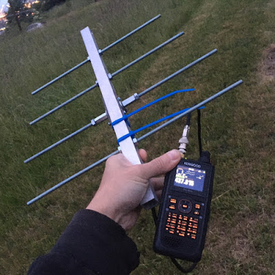
The APRS Antenna attached to the payload

The K.C.A.R Kite Payload exposed


 (Click on images for larger view.)


This is the final part of the Kite Carrying Amateur Radio Research Project.  Due to aviation legislation and safety rules I was never able to fly the kite from the Riversdale Airport.  However we had good fun with the project.  This was a great learning curve for me and those that participated.

Johan ZS1I - Mossel Bay 2008

Maintenance: Amateur Radio Mast at the Coast

  Over a period of time I noticed that one of my radio masts (Ex Wind Turbine Mast) was showing signs of rust where two pipes were welded to...