(Click on image for larger view.)
I always seem to look for a simple crowbar circuit to protect my radios and other electronic equipment from over-voltage and reverse polarity. Now I know there are many types of crowbar circuits that provides many types of protection. I did not want to "re-invent the wheel" relating to crowbar circuits. In Project 1 I used the well known MC3423 Chip and a few other components. More information available HERE.
In the images below is a protection circuit I found on the Internet. It blows the fuse if the voltage from the power supply rises above 15 Volts. It uses a 20 Amp thyristor so it’s more than capable of blowing a 15 Amp fuse. I’m using a 10 Amp fuse because that’s all I had. Also, most of my equipment running from this power supply aren’t current hungry. (More on the modified power supply in a future posting.) By the way, I wouldn’t rely on the modified power supply’s short circuit protection to cut the power. I decided to use fuses instead of using a relay. Once again some say a relay is better than a fuse. I used what I had on hand!
I decided to add a TVS diode (transient voltage suppression diode) as used in the original design, as this would appear to make the BT152 thyristor redundant. If the TVS diode conducts at 15 Volts then, why use a thyristor? Well why not use double protection? I suppose the TVS diode is fast when dealing with transient voltages. The TVS diode also protects against an accidental reverse polarity voltage connection.
Now before you running of to build the Crowbar a word of warning!! Using Vero Board is fine, but do bear in mind that the thin copper strips are not designed to carry 20 or 30 Amps! To solve this problem, I ran 3mm tinned copper wire alongside the heavy current-carrying strips. I also joined (soldered) clean tracks together that carry the 12 Volt in/out of the board. The board can now easily carry the 15 Amp current without any issues. If you upscale the Thyristor and other components for higher current then I would advise not to use Vero Board. Dead Bug Style or a PCB might be considered.
Parts List:
1.5KE 15 TVS 1.5kW 15v Diode
BT152 Thyristor 800v 20 Amp
27K 1 watt Resistor
10 Ohm 1 watt Resistor (I used a 2 watt that I had)
1 uF 50v Radial Electrolytic Capacitor
1N5245B Zener Diode 15v 1 watt
Vero Board (65mm x 35mm)
Red and Black Flex Wire (Copper diameter = 2 - 3 mm)
Optional:
Black and Red Terminal Posts
2 x Fuse Holders
2 x 10 Amp Fuses
1 x LED Holder
1 x Red LED
1 x 330 Ohm 1/4 watt Resistor for LED
1 x Project Cabinet
1 x Black Compression Gland 12.5mm CAB = 4-8mm

(Click on image for larger view.)
Construction:
Constructing this Crowbar is straight forward as indicated by the diagram and images.
Information on the two fuses. I used normal automotive fuses which I had in my component cabinet. I would however advise using good semiconductor fuses on the 13.8v input line to protect the SCR. The I2T rating of the fuse should be less than that of the SCR. You have been warned!!
What is a Semiconductor Fuse? Also known as ultra-rapid fuses, high speed fuses or rectifier fuses; a Semiconductor fuse is a high speed current limiting fuse that is designed to protect and isolate sensitive semiconductor components such as diodes, thyristors, SCRs etc. by minimizing the I²t, peak current let-through and arc voltage.
Summary:
I recommend you construct this unit that provide over-voltage and reverse voltage protection and fusing. This unit will ensure that your equipment is protected from inadvertent power supply transients, power supply over voltage failures or connection mistakes like reverse polarity.
Note: I will provide more information about the working of the Crowbar in a future article.
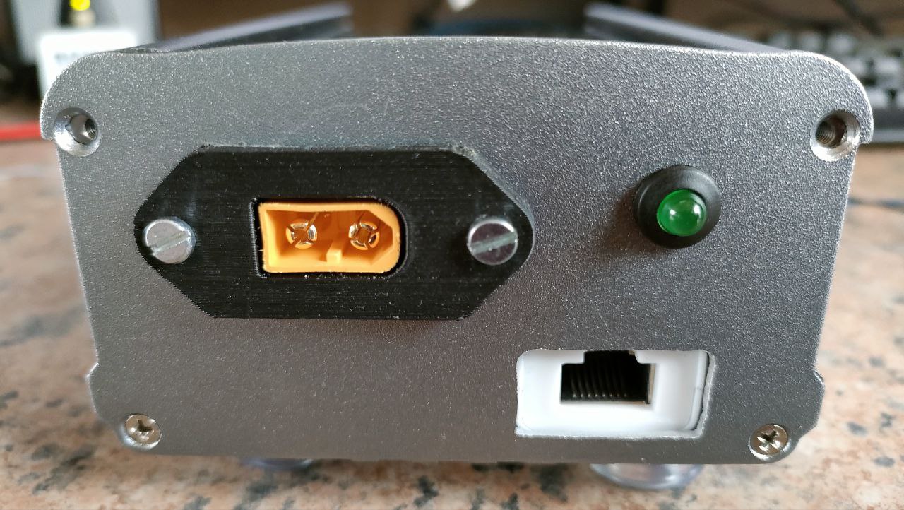
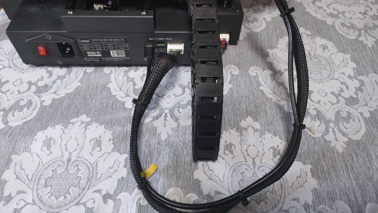
Images: (Click on images for larger view.)