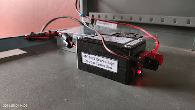
Many years ago I constructed the Marchwood Power Supply published in Practical Wireless. Article available HERE. At the time this was the "Rolls Royce" of heavy duty power supplies. In my humble opinion this is still the case despite the many switch mode and other power supplies available on the market today. I decided to use a switch mode power supply for the GRHub Network link radio and accessories. Having two other homebrew power supplies with soft start and several protection circuits does however not work great when loadshedding is implemented, as you need to restart the power supplies manually after power returns. I was looking for a solution to solve this "problem" but did not want to modify my old power supplies in any way. Looking at the box of a Chinese 20 Amp Switch Mode Power Supply it shows that the unit has all sorts of protection circuitry that will protect you expensive equipment. Having experienced issues in the past with writing on packaging and what is actually built into a product is another kettle of fish. I looked at the Marchwood Power Supply's over voltage protection circuitry but did not want to go the route merely out of a cost aspect. I wanted something effective yet it must be a KISS project as many of my other projects are. Now I know there is many other crowbar circuits out there but out of a nostalgia point of view I wanted a circuit that uses the MC3423 IC and BT151 SCR as I had all the parts in my component boxes.
I searched on the Internet for a simple circuit and found a Wind Turbine Crowbar Emergency Stop circuit that would also work on a power supply. Well the rest is history and I am not going to explain the build in detail as the diagrams, photos and videos explain what needs to be explained. I added a visual indication (LED) when the SCR switches. Construction for me was rather tedious and not because it is difficult. Old age and bad eyesight makes it very difficult to build something on Veroboard these days. After this project I have decided to stop using Veroboard for any project. Well that is enough talk for now. At the end of the photos and before the videos I will provide more information regarding component calculations, use of a fuse to protect the SCR and setting a faster delay speed for the unit.
Component List:
R1 = 47K
R2 = 10K
R3 = 1K3
R4 = 20 Ohm
D1 = Red LED
IC = MC3423
Heatsink for BT151
8 Pin IC Socket
SCR = BT151 (Alternatives: BT152, 2N6507G 25 Amp)
Connecting wire
Project Box (I printed a 3D Project Cabinet for this project.)
Connecting Terminal (Output)
Wire Gland (Input)
Screws
Cabinet Feet
Odds and Sods for soldering etc.
Images (Click on images for larger view.)
Updated Images reflecting final installation of the Crowbar Protection Unit:
The power supply and over voltage crowbar protection unit are now used to provide power to the GRHub Network and DMR Bridge, Mossel Bay.
Calculations:
As mentioned supra here is the calculations for R1, R2 and R4.
R1 and R2 Calculations:
13.8 (Vtrip) = 2.6 (Vref) (1 + R1 over 10 000 (10K)
2.6 (1 + R1 over 10 000 (10K) = 13.8V
13.8 devided by 2.6 = 5.307 - 1 = 4.307
4.307 x 10 000 (10k) = 43.070 (use 47K for R1 or substituted for a 50K POT)
Results:
R1 = 47K or 50K POT
R2 = 10K fixed resistor
R4 Calculations:
R4 = Vtrip over 10mA
R4 = 13.8 (volts) over 10 (mA) = 1K3
Result:
R4 = 1K3 fixed resistor
Final Comments:
1. Crowbar operates at ~14.3V
2. Switching Delay = 1.0 uS. For faster switching connect Pin2 to Pin3. Pin 4 is left floating. Circuit switching delay will then be 0.5 uS
3. BT151 must be fitted with a large enough heatsink.
4. If your power supply or circuit is not current limited the SCR will go up in smoke. You need a good semiconductor fuse on the 13.8v input line to protect the SCR. The SCR does get very hot and will go up in smoke. The I2T rating of the fuse should be less than that of the SCR. You have been warned!!
What is a Semiconductor Fuse?
Also known as ultra-rapid fuses, high speed fuses or rectifier fuses; a Semiconductor fuse is a high speed current limiting fuse that is designed to protect and isolate sensitive semiconductor components such as diodes, thyristors, SCRs etc. by minimizing the I²t, peak current let-through and arc voltage.
What is the I 2t value of a fuse?
Fuse I2T Rating, Melting Point, and Interrupt Rating.
The I²t (Ampere Squared Seconds) also known as Melting Point in a fuse. The purpose of this rating is to assure that the heat created across the fuse during a surge has insufficient time to thermally conduct away from the fuse to external circuitry. Once the measurements of current (I) and time (t) are determined, it is a simple matter to calculate melting I2t. When the melting phase reaches completion, an electrical arc occurs immediately prior to the “opening” of the fuse element.
The higher the Melting Point (I2t) the longer the fuse will take to open. More info regarding this can be found with a Google search on the Internet.
5. Use thick enough wire for the input and output of this circuit.
Videos:
End.


