Saturday, April 30, 2022

Changes to the GRHub Network 145.550 Mhz Simplex RF Link audio quality! (Part 1)


  For a while now I received the following "complaints" from users of the GRHub Network:

  • Very low level audio quality in the George area via the 145.550 Mhz Simplex  RF Link.  Strong signal but audio is very low.
  • Some users of the 145.550 Mhz Simplex Link are over modulating and very "scratchy".  So much so that Echolink and AllStar users cannot have and a normal QSO with these stations when they are on the RF Link.

Now this was a real head scratcher as I tried to correct the audio levels for all the systems that I am currently running from Mossel Bay.  Remember I run Echolink, AllStar  and the RF Link all at the same time.  At first I had to ascertain where the problem lies.   This is not a plug and play system!  I had to work systematically through all the systems to ensure that each one is working as it should and that the audio level is set correctly for each VOIP system and the RF Link.  I did quite a lot of reading on setting the audio levels for different functions.  Yes, remember I also had to ensure that all the telemetry, announcement and DTMF audio levels are set correctly.

This afternoon (29 April 2022) I overheard Michael ZS1MMB (George) and ZS6?? and ZS6IW talking.  Michael was using the 145.550 Mhz RF Link into Echolink and AllStar.  Both ZS6 stations indicated that Michael was over-modulating so much so that Michael had to revert to Echolink on his cellphone. This problem had to be solved methodically.  I started on the VOIP (Internet) side of things.  Echolink was first in the line-up.  But there were no stations to test with.  Well I used the Echo-Test Server, the Enrico TM8 and a handheld 2m radio. I then moved to AllStar using the UK AllStar Parrot Node and did the same tests using the same equipment.  I also listened "cross linked" to the audio via VOIP.  The audio was clear and no over modulating occurred.  Now it was the time to test the 145.550 Mhz RF Link.  I use an old Motorola Radius Radio.  I had it on the test bench a few weeks ago to test the radio which included the FM deviation frequency and all the other test settings, to many to mention here.  After a clean bill of health for the radio the only thing left to test and setup was the simple-usb-tune menu in Asterisk.  Two settings of interest that I will be looking into was the Set RX Voice Level, using the audio display and Set Transmit A Level.

I first tested the Set Transmit A Level setting it to the lowest setting.  I could immediately notice a difference on the RF Link.  The audio level were very low.  I played around with the settings until I was finally satisfied with the transmit level.  This should solve the low level audio in the George and other areas with a far louder audio level.  Now was the turn for the Set RX Voice Level using the audio display.  Now how do I accomplish this if their is no stations to test with.  Again the parrot functions solved this.  I set this level to 5 the lowest I can go.  I immediately noticed a difference in the audio quality, no clipping or over modulation on my side.  The proof will be in the pudding once those stations that experienced over modulation uses the RF Link again.  I am quite confident that this settings solved the issues. In the event that it did not I have one other trick up my sleeve but more on that if these settings did not correct the current issues.  I learned quite a lot this past week and today.  It is not as simple as just setting up a radio, switch it on and there you go.  No all these systems must work in "harmony" to give you the prefect performance and audio. I would like to encourage stations to use the 145.550 Mhz RF Link in the Mossel Bay area to test the new settings.  Hopefully the over modulating and soft audio issues are now solved.  Please let me know if you still experience issues.


Friday, April 29, 2022

Setting up a DVSwitch Server for an AllStar to DMR Bridge


 Now what is a DVSwitch Server and why would I set it up?  In short it is to setup a DVSwitch server and use your Android phone as a DMR radio through a digital-analog bridge.

DVSwitch is a Client-Server application for Amateur Radio Digital Voice. The application provides a “Server” component which runs on a Raspberry Pi (RPi) or other Linux platform. It can also be installed on a cloud server running Linux. The server component is distributed as an RPi image with all features and functions installed. Therefore, no additional modules or programs need to be downloaded installed for a Raspberry Pi. There are two clients available for DVSwitch. An Android client is available on the Google App store for virtually any type of Android device. In addition, the python Client (pyUC) is available to use on Windows, or Mac.The ultimate aim here is to experiment with analog-to-digital bridges, but setting up a DVSwitch server could be useful in many amateur radio instances. DVSwitch Mobile enables you to use your Android smartphone as a “radio” to access digital networks, such as BrandMeister DMR TalkGroups, YSF Reflectors, XLX, NXDN, and more.
  • Your smartphone is your “radio”
  • The  DVSwitch server is your “hotspot”

DVSwitch supports all current Digital Voice modes with no additional hardware with the exception of D-Star. For D-Star, an external hardware Vocoder such as the Northwest Digital ThumbDV dongle. For other modes, the software Vocoder included in DVSwitch provides high quality audio While DVSwitch has been in use for sometime but the installation was somewhat complex and was mostly used by computer “geeks”. With this release, an average ham can be up and running in less than 10 minutes. This release provides many new features including the ability to switch modes dynamically, customize Talk Group, Room, and Reflector lists from either the server or client and dynamically switch among DMR networks such as Brandmeister, TGIF, QRM, etc. The DVSwitch installation described in the link underneath entails using a Raspberry Pi image. If you choose, you may install DVSwitch on an existing Linux installation. This gives you the option of using a platform other than a Rasbpberry Pi as well as using a platform that as a full GUI or other software.I did not want to install the server to a cloud but rather on a Raspberry Pi. Now how do one install DVSwitch-Server on a Raspberry Pi. You can find a very comprehensive manual HERE. 

I successfully installed the DVSwitch Server on a Raspberry Pi 3b and setting up DVSwitch Moble on my smartphone.  I conducted several tests yesterday relaying (RX Mode only) DMR to AllStar and Echolink and onto the ZS-Link Network.  As can be seen from the images underneath several stations were heard via the system.  Even a South Korean station   DS4AKP  were heard.  The server is working well and I will now move on to the second task in establishing an AllStar to DMR Bridge.  More on this in a future posting.Finally:  Why would I want to build a bridge between Analog and Digital?  Simple answer this will create more activity on our local amateur radio bands.  I have not yet decided how the bridge would be slot into the current link network.  One possible idea is to create a free standing node that can be switched in an out as needed.  This will ensure that the ZS-Link network is free to use by local radio amateurs.  Stay tuned! (Click on images for larger view.)


Thursday, April 28, 2022

10 Meter Band wide open - 27 April 2022


The 10 meter band is wide open with plenty of activity around.  Thys ZS1TBP send me videos as confirmation.    Here is some interesting information on the 10 Meter band.

The 10-meter band is a portion of the shortwave radio spectrum internationally allocated to amateur radio and amateur satellite use on a primary basis. The band consists of frequencies stretching from 28.000 to 29.700 MHz.

The 10-meter band was allocated on a worldwide basis by the International Radiotelegraph Conference in Washington, D.C., on October 4, 1927. Its frequency allocation was then 28-30 MHz.

A 300 kHz segment, from 29.700 MHz to 30.000 MHz, was removed from the amateur radio allocation by the 1947 International Radio Conference of Atlantic City.

In the late 1970s, the impending ban by the FCC of the sale of older 23-channel CB equipment that did not meet more stringent restrictions on newer, 40-channel units, meant that a surplus of 23-channel CB gear was on the market. This was a windfall for amateur radio enthusiasts, allowing access to fairly inexpensive radios which could easily be modified for use in the 10-meter band.

American Novice- and Technician-class licensees were granted CW and SSB segments on the 10-meter band as of 00:01 UTC March 21, 1987. Being a very wide band in HF terms, many different transmission modes can be found on 10 meters. Morse code and other narrowband modes are found toward the bottom portion of the band, SSB from 28.300 MHz up, and wideband modes (AM and FM) are found near the upper part of the bottom portion of the band. Digital modes, such as PSK-31, are also allowed in the upper portion of the band, with 28.120 being a popular PSK-31 frequency.

With the elimination of Morse code testing requirements for U.S. amateurs in February 2007, Technician-class licensees who have not passed a code test may operate with up to 200 watts PEP using CW and SSB modes in a portion of the 10-meter band.

Due to its unique spot in the spectrum, 10 meters can occasionally be challenging to work. At peak times of the solar cycle when many sunspots appear on the Sun's surface, 10 meters can be alive with extremely long-distance signals, refracting from the F2 layer in the ionosphere. Generally speaking, the most effective and efficient propagation of 10-meter radio waves takes place during local daylight hours. During periods of increased sunspot activity, band openings may begin well before sunrise and continue into the night.

Long-distance opportunities via F2 seem to follow the sun across the globe. In North America, for instance, F2 might bring Europe and western Asia in the morning, the Americas during midday, and the Pacific and East Asia in late afternoon and early evening.

Even in times of solar minimum, when F2 is rarely available, 10 meters still has some long distance possibilities. Sporadic E propagation can bring in signals from a hundred to many thousands of miles away. Sporadic E on 10 meters is mainly a seasonal event, with late spring and early summer being prime time for the mode. A shorter, less-intense period occurs during mid-winter, often between Christmas and the new year. Other, off-peak openings may be seen almost anytime. Even during solar minimum, F2 openings often occur on transequatorial paths, for example between Europe and Southern Africa or between Pacific North America and the Eastern Pacific islands.

In tropical latitudes 10 meters is open throughout the sunspot cycle, although propagation is often confined to other areas lying along the equator. For example, a good path from West Africa to the Caribbean exists on 10 meters even at solar minimum.


 Why not join the 10-10  International?  Ten-Ten International (or 10-10 for short) is a worldwide amateur group dedicated to the 10 metre band, which offers club and membership information, news, forums, activities, awards and links.  Click HERE for more information.


Finally:  In the last solar cycle 24 peak a worked hundreds of stations on the 10 meter band with a wire Delta Loop.  Give the 10m band a try.  You will be quite surprised about the activity on this amateur radio band.

Wednesday, April 27, 2022

Removable VHF/UHF Car Window Antenna for Amateur Radio Emergency Communications

I build this antenna several years ago while I administered the South African Weather and Disaster Information Service (SAWDIS).

Emergency Radio Communications forms part and parcel of the SAWDIS. Being a member of HAMNET requires that members be able to provide emergency radio communications during severe weather and disasters. Having used a mag-mount antenna for years, I decided that this was not the way to go when I recently purchased a new vehicle. The damage caused to the paint of the car and an ever lasting cable running from the roof to the car was just not viable any more. Drilling a hole was definitely not an alternative option. I considered buying a commercial antenna but due to the high cost, decided against buying a commercial manufactured antenna.

It is often difficult to install a two way radio and its associated antenna in a modern motor vehicle. In many cases a challenge is establishing a connection between the antenna on the outside of the vehicle and the radio inside, without drilling holes in the vehicle's body.

I decided to build a removable car window antenna with cross over connector. This mount is designed to provide a quick removable antenna system. That, combined with a VHF/UHF radio equipped with a plug designed for what used to be called a cigarette lighter socket, should be all it takes to set up temporary operation for emergency radio operations.

I started building the antenna about three weeks ago, but was interrupted many times which prohibited me from finishing the antenna in one or two days. I eventually finished the antenna over the weekend and put it to test yesterday afternoon while driving to George using a Yaesu VX-7R hand held as the transceiver. Tests were carried out with the help of Johan ZS2I and Willie ZS2CC. Reports received indicated that this antenna works exceptionally well and worth all the effort made to "homebrew" this antenna for emergency radio operations. A final bonus is the fact that the antenna and radio can be removed in a few seconds when not in use.

Herewith some pictures of my handywork.


Images: SAWDIS (Click for larger view.)

Design: Jean-Yves Morin, VE2MHZ - Removable Car Window Antenna with Cross Over Connector   PDF file for download supplied by Johan van Aarde ZS2I

Tuesday, April 26, 2022

2 Meter Low Power TX For ARDF (Fox Hunting)


Several years ago I decided to build myself this 2M low power ARDF transmitter as described by ON7YD.

This is an easy to build and low cost 144MHz mini transmitter that produces a remarkable 'clean' 144MHz signal up to 15 mW. It can also be used as exciter to drive a PA. In combination with a good UHF transistor a 2 transistor 200mW TX can be build or in combination with one of those power modules that are used in handies several Watts can be produced.

With a low cost 24MHz xtal the oscillator runs on the 3rd overtone (72MHz). The collector circuit acts as a doubler. In this type of oscillator the xtal oscillates well above it's natural frequency, resulting in a end frequency of +/- 144.070MHz for a 24MHz xtal. Any other 72MHz xtal can be used, but a lot of these xtals are 5th overtone. In this case L1 should be reduced to 0.47ĀµH to avoid that the xtal will run on the 3rd overtone.

The oscillator is modulated with a mixture of AM and FM, so both AM or FM receivers can be used.


COMPONENT LIST:
IC1 4093 (CMOS)            
TI  2N918
T2  BC557C
X1  24 MHz
L1  1uH
L2/3  5 wind of 1mm wire, diameter 5mm, tapped at 1 wind from the cold end.
R1  39K
R2  1M
R3  10K
R4  330K
R5  1M
R6  1K
C1  47pF
C2  15pF
C3/4  3-20pF
C5  1n
C6  47n
C7  470n
C8  100n


The oscillator is built around T1, with a 24 MHz xtal used on the 3rd overtone (72 MHz). The collector circuit acts as a frequency doubler and the critical coupled double band pass filter (L2, L3, C3, C4) makes sure that all (sub)harmonics are at least 40 dB below the carrier. C3 and C4 have to be adjusted for maximum output power.
With R2 the output power of the oscillator can be adjusted between 0.1 and 15 mW.
The 2 Schmitt-Trigger NAND gates of the 4093 produce a intermittent LF tone that is used to modulate the oscillator. The remaining gates are disabled by pulling their inputs to plus.
With R6 the modulation level can be adjusted.

Output power vs. supply voltage and current
supply voltage supply current output power
15 V 14mA 15 mW
12 V 11mA 9 mW
9 V 9mA 5mW
9 V 4.5mA 3mW
9 V 2.5mA 1mW


Above: Photos of the 2M Fox TX.

ABOVE:  Simple 2M Beam Antenna which I use to track the fox.


Above:  2M RX showing the fox in action on a frequency of 144.0875 Mhz NFM. 

(Click on images for larger view.)

NOTES:   The transmitter was tested extensively.  This transmitter is ideal for a small to medium range field.  This unit was tested in a 1km radius using the beam antenna for RX and a J-Pole as the TX for the transmitter. I could easily copy the signal even though there were buildings in the way.  The bonus of the antenna I used for receive is that you can either use the antenna horizontally or vertically polarized.  The TX emits a continues carrier with a very good audible beep.   This unit is ideal for a beginner TX to promote ARDF .  The bonus is that you can use several of these units in a small to medium field.  The unit is small and easy to construct.

Monday, April 25, 2022

Technology: Testing electrical motors with a Spectrum Analizer - Lionel ZS6DPL

In a recent posting Lionel  ZS6DPL  uploaded two videos to the Amateur Radio 101 Telegram group.  Lionel explained what his work entails and how he uses a spectrum analyzer to test electrical motors. 

Now what is a spectrum analyzer? 

A spectrum analyzer measures the magnitude of an input signal versus frequency within the full frequency range of the instrument. The primary use is to measure the power of the spectrum of known and unknown signals. The input signal that most common spectrum analyzers measure is electrical; however, spectral compositions of other signals, such as acoustic pressure waves and optical light waves, can be considered through the use of an appropriate transducer. Spectrum analyzers for other types of signals also exist, such as optical spectrum analyzers which use direct optical techniques such as a monochromator to make measurements.

By analyzing the spectra of electrical signals, dominant frequency, power, distortion, harmonics, bandwidth, and other spectral components of a signal can be observed that are not easily detectable in time domain waveforms. These parameters are useful in the characterization of electronic devices, such as wireless transmitters.

The display of a spectrum analyzer has frequency on the horizontal axis and the amplitude displayed on the vertical axis. To the casual observer, a spectrum analyzer looks like an oscilloscope and, in fact, some lab instruments can function either as an oscilloscope or a spectrum analyzer.  More on spectrum analizers can be found HERE.

The following is a short overview of testing electrical motors:

There’s a huge range of diagnostic tools available for pinpointing motor issues — clamp-on ammeters, temperature sensors, Meggers, winding analyzers, spectrum analysers and oscilloscopes, just to name a few. And depending on the specific area of trouble, each tool can help illuminate the problem in different ways.

A good rule of thumb for troubleshooting a motor is to first rely on your senses: Is the motor hot or overheating? Does it smell or sound unusual? Is it physically behaving in an erratic way? To begin an evaluation, check in first on the basic measures of motor performance: current levels, power, voltage, and resistance.

Preliminary tests are generally done using the ubiquitous multimeter, which can provide diagnostic information for all kinds of motors.

Complex, powerful tools, electric motors are critical components in a wide range of equipment and tools, from the smallest electronic fans to the largest manufacturing and industrial equipment. Without motors, many basic industrial functions would be severely compromised, if not impossible; motors are the heartbeat of daily work.

Motor failure, therefore, can be extremely costly and disruptive, resulting in unscheduled downtime and unplanned maintenance costs. But by dedicating time to thorough motor testing — both in regular, routine maintenance programs and at the first sign of trouble — motor issues can be reliably predicted, prevented, isolated, and resolved with minimal service disruption. 

Below are the two videos that Lional provided of  the type of work he is doing and how he uses technology to to assist him in fault finding.  Lionel thank you very much for the videos and a look in how you can analyze electrical motors before running into serious failures and high replacement costs.

I trust that our readers will find this technology article interesting.  I did and learned several new things that I did not know before.


Sunday, April 24, 2022

Important Notice: The NSN - Net #12 moves to a new day and timeslot


Important Notice:  The NSN - Net moves to a new day and time-slot. 

This move is necessitated by the fact that many participating radio amateurs experience connection issues on a Thursday evening as the Net takes place during the peak Internet usage period.  We cannot afford to leave radio amateurs in the cold and unable to participate.

It was therefor decided to move the NSN - Net to a Sunday afternoon after the "Bo Karoo Amateur Radio Klub" Bulletin which takes place every Sunday at 15h00.    The NSN - Net will take place 10 minutes after the BK Bulletin.  This will allow for the make of a nice cup of coffee between the two events.  Another benefit would be that those connected to the ZS-Link Network need not disconnect from Echolink and can just continue with the NSN - Net.

Several radio amateurs expressed their satisfaction to the new day and time-slot as hopefully this will allow them to participate in the NSN - Net.  It is hoped that the connection issues experienced by some will be solved and that we can continue with our interesting topics and discussions.

Summary:

NSN - Net will now take place on a Sunday afternoon 10 minutes after the Bo Karoo Amateur Radio Klub bulletin.

We will continue with the NSN - Net as before.

The first NSN - Net on a Sunday will take place on the 1 May 2022. Further reminders will be posted in this regard.

The weekly topic question will be:

"Do we need all the analog and digital amateur radio repeaters currently installed and operational in South Africa?  Looking at the usage and cost to install and maintain these repeaters, should we still build repeaters and repeater networks?"

"Word analoog en digitale amateur radio herhalers wat tans geinstalleer en in gebruik is, steed benodig in Suid Africa?  As daar gekyk word na die gebruik  en kostes om 'n herhaler te installeer en te onderhou, moet ons voortgaan om herhalers en herhaler netwerke te installeer?"

We hope to welcome more radio amateurs to the NSN Net on a Sunday afternoon and trust that we will not lose any of our regular participants due to the new day and time-slot. 

You can access the Net as follow:

  • Echolink - Connect to ZS1I-L, ZS1FC-L, ZS3KBY-R or ZS5PMB-R Please note if the last 3 stations is not connected to ZS1I-L then you need to connect to ZS1I-L for the NSN Net.
  • AllStar - Connect to node 49355
  • VHF - 145.550 Mhz Simplex in the Mossel Bay area. Remember the 88.5 khz CTCSS tone
  • Any other Echolink, AllStar repeater or link station that is connected to either ZS1I-L or node 49355
  • Use of your cellphone by installing Echolink on your phone
  • By means of a Network Radio example Enrico TM8 etc.

Hope to hear you on the NSN Net!!

The SARL 2022 Annual General Meeting relayed on Echolink ZS1I-L and 43955 AllStar - ZS-Link Network


The SARL 2022 Virtual Annual General Meeting took place from 10h00 to 12h55 yesterday at the National Amateur Radio Centre, Johannesburg.  The attendance via the Blue Jeans Virtual Platform was well supported 252 radio amateurs registered and between 101 - 114 participants logged in. It was great so see so many members that supported the event. 

I am not going to report on the outcome of the meeting as this will be done via several bulletins and other amateur radio media outlets.  You can now download the 2022 SARL Annual Report in PDF format HERE.  

Image: The AGM presented from the NARC - Source:  Rassie ZS1YT

 
The meeting was a great success and I would like to thank  Nico van Rensburg ZS6QL, SARL President, Chris Turner ZS6GM, SARL Vice President, Dennis Green ZS4BS, SARL Secretary, Hans van den Groenendal ZS6AKV (Blue Jeans)  and all those who were responsible for the arrangements etc.  It was really a pleasure to listen live to the meeting.

While I had the privilege to join the Blue Jeans Platform to listen to the proceedings, there were many out there that either could not join via Blue Jeans for several reasons beyond their control.  This is why I decided to relay the audio of the meeting live on the ZS-LINK Network via Echolink ZS1I-L and 43955 AllStar as well as 145.550 Mhz Simplex in the Garden Route Area.  The audio quality coming from Blue Jeans was great and this was also portrait on the ZS-Link Network.  Several stations connected even overseas stations as can be seen from the log image underneath.

There was also a relay on 40 meters done by Chris ZS6GM with several radio amateurs that reported in.

File: /var/log/asterisk/connectlog
-----------------------------------------------------------------
List of call-ins on ZS1I-L Echolink and 49355 AllStar - 2022 SARL AGM

1. Please take note there is some duplication as some stations log in and out.
2. Several overseas stations also logged in during the proceedings.

Sat Apr 23 10:00:55 SAST 2022 == 49355 Connected AllStar 542871 <=IN== ZS6CMO 435.850 Alberton
Sat Apr 23 10:05:40 SAST 2022 == 49355 Connected EchoLink 3822881 <=IN== ZR6XL [EchoLink 822881]
Sat Apr 23 10:06:00 SAST 2022 == 49355 Connected EchoLink 3532035 <=IN== ZS1NEU [EchoLink 532035]
Sat Apr 23 10:06:15 SAST 2022 == 49355 Disconnected EchoLink 3532035 =v= ZS1NEU [EchoLink 532035]
Sat Apr 23 10:08:06 SAST 2022 == 49355 Connected EchoLink 3822881 <=IN== ZR6XL [EchoLink 822881]
Sat Apr 23 10:10:28 SAST 2022 == 49355 Disconnected AllStar 542871 =v= ZS6CMO 435.850 Alberton
Sat Apr 23 10:11:59 SAST 2022 == 49355 Connected EchoLink 3410265 <=IN== ZS5ZP [EchoLink 410265]
Sat Apr 23 10:13:13 SAST 2022 == 49355 Connected EchoLink 3518428 <=IN== ZS1PDY [EchoLink 518428]
Sat Apr 23 10:14:06 SAST 2022 == 49355 Disconnected EchoLink 3518428 =v= ZS1PDY [EchoLink 518428]
Sat Apr 23 10:16:58 SAST 2022 == 49355 Connected EchoLink 3957101 <=IN== ZS6DDM [EchoLink 957101]
Sat Apr 23 10:17:47 SAST 2022 == 49355 Disconnected EchoLink 3789457 =v= ZS1JFK [EchoLink 789457]
Sat Apr 23 10:18:29 SAST 2022 == 49355 Disconnected EchoLink 3957101 =v= ZS6DDM [EchoLink 957101]
Sat Apr 23 10:19:32 SAST 2022 == 49355 Connected EchoLink 3339240 <=IN== ZR2CIA [EchoLink 339240]
Sat Apr 23 10:19:48 SAST 2022 == 49355 Disconnected EchoLink 3822881 =v= ZR6XL [EchoLink 822881]
Sat Apr 23 10:21:04 SAST 2022 == 49355 Disconnected EchoLink 3339240 =v= ZR2CIA [EchoLink 339240]
Sat Apr 23 10:22:09 SAST 2022 == 49355 Connected EchoLink 3339240 <=IN== ZR2CIA [EchoLink 339240]
Sat Apr 23 10:24:44 SAST 2022 == 49355 Connected EchoLink 3242320 <=IN== ZS6KED [EchoLink 242320]
Sat Apr 23 10:25:13 SAST 2022 == 49355 Connected EchoLink 3822881 <=IN== ZR6XL [EchoLink 822881]
Sat Apr 23 10:26:59 SAST 2022 == 49355 Disconnected EchoLink 3822881 =v= ZR6XL [EchoLink 822881]
Sat Apr 23 10:27:35 SAST 2022 == 49355 Connected EchoLink 3531797 <=IN== ZS4DZ [EchoLink 531797]
Sat Apr 23 10:29:45 SAST 2022 == 49355 Disconnected EchoLink 3531797 =v= ZS4DZ [EchoLink 531797]
Sat Apr 23 10:29:53 SAST 2022 == 49355 Connected EchoLink 3531797 <=IN== ZS4DZ [EchoLink 531797]
Sat Apr 23 10:34:40 SAST 2022 == 49355 Connected EchoLink 3728527 <=IN== ZS5YH [EchoLink 728527]
Sat Apr 23 10:35:04 SAST 2022 == 49355 Disconnected EchoLink 3728527 =v= ZS5YH [EchoLink 728527]
Sat Apr 23 10:36:08 SAST 2022 == 49355 Connected EchoLink 3728527 <=IN== ZS5YH [EchoLink 728527]
Sat Apr 23 10:43:05 SAST 2022 == 49355 Disconnected EchoLink 3339240 =v= ZR2CIA [EchoLink 339240]
Sat Apr 23 10:43:14 SAST 2022 == 49355 Connected EchoLink 3339240 <=IN== ZR2CIA [EchoLink 339240]
Sat Apr 23 10:56:48 SAST 2022 == 49355 Disconnected EchoLink 3531797 =v= ZS4DZ [EchoLink 531797]
Sat Apr 23 10:57:05 SAST 2022 == 49355 Connected EchoLink 3531797 <=IN== ZS4DZ [EchoLink 531797]
Sat Apr 23 11:08:23 SAST 2022 == 49355 Disconnected EchoLink 3339240 =v= ZR2CIA [EchoLink 339240]
Sat Apr 23 11:08:38 SAST 2022 == 49355 Connected EchoLink 3339240 <=IN== ZR2CIA [EchoLink 339240]
Sat Apr 23 11:10:06 SAST 2022 == 49355 Disconnected EchoLink 3531797 =v= ZS4DZ [EchoLink 531797]
Sat Apr 23 11:10:14 SAST 2022 == 49355 Connected EchoLink 3531797 <=IN== ZS4DZ [EchoLink 531797]
Sat Apr 23 11:11:08 SAST 2022 == 49355 Disconnected EchoLink 3339240 =v= ZR2CIA [EchoLink 339240]
Sat Apr 23 11:11:40 SAST 2022 == 49355 Connected AllStar 542871 <=IN== ZS6CMO 435.850 Alberton
Sat Apr 23 11:11:44 SAST 2022 == 49355 Connected EchoLink 3339240 <=IN== ZR2CIA [EchoLink 339240]
Sat Apr 23 11:15:39 SAST 2022 == 49355 Disconnected EchoLink 3242320 =v= ZS6KED [EchoLink 242320]
Sat Apr 23 11:15:46 SAST 2022 == 49355 Connected EchoLink 3242320 <=IN== ZS6KED [EchoLink 242320]
Sat Apr 23 11:15:54 SAST 2022 == 49355 Disconnected EchoLink 3242320 =v= ZS6KED [EchoLink 242320]
Sat Apr 23 11:16:09 SAST 2022 == 49355 Connected EchoLink 3242320 <=IN== ZS6KED [EchoLink 242320]
Sat Apr 23 11:16:19 SAST 2022 == 49355 Disconnected EchoLink 3339240 <=IN== ZR2CIA [EchoLink 339240]
Sat Apr 23 11:16:20 SAST 2022 == 49355 Connected EchoLink 3339240 <=IN== ZR2CIA [EchoLink 339240]
Sat Apr 23 11:17:27 SAST 2022 == 49355 Disconnected AllStar 542871 =v= ZS6CMO 435.850 Alberton
Sat Apr 23 11:17:58 SAST 2022 == 49355 Connected EchoLink 3386178 <=IN== K1ZHD [EchoLink 386178]
Sat Apr 23 11:18:54 SAST 2022 == 49355 Connected EchoLink 3875148 <=IN== ZL2OHM [EchoLink 875148]
Sat Apr 23 11:19:20 SAST 2022 == 49355 Disconnected EchoLink 3386178 =v= K1ZHD [EchoLink 386178]
Sat Apr 23 11:22:20 SAST 2022 == 49355 Disconnected EchoLink 3875148 =v= ZL2OHM [EchoLink 875148]
Sat Apr 23 11:22:30 SAST 2022 == 49355 Disconnected EchoLink 3531797 =v= ZS4DZ [EchoLink 531797]
Sat Apr 23 11:24:03 SAST 2022 == 49355 Connected EchoLink 3531797 <=IN== ZS4DZ [EchoLink 531797]
Sat Apr 23 11:25:15 SAST 2022 == 49355 Disconnected EchoLink 3531797 =v= ZS4DZ [EchoLink 531797]
Sat Apr 23 11:26:32 SAST 2022 == 49355 Connected EchoLink 3531797 <=IN== ZS4DZ [EchoLink 531797]
Sat Apr 23 11:27:08 SAST 2022 == 49355 Connected EchoLink 3518428 <=IN== ZS1PDY [EchoLink 518428]
Sat Apr 23 11:27:53 SAST 2022 == 49355 Disconnected EchoLink 3242320 =v= ZS6KED [EchoLink 242320]
Sat Apr 23 11:29:20 SAST 2022 == 49355 Connected EchoLink 3259015 <=IN== ZS6VOL [EchoLink 259015]
Sat Apr 23 11:29:42 SAST 2022 == 49355 Disconnected EchoLink 3339240 =v= ZR2CIA [EchoLink 339240]
Sat Apr 23 11:30:03 SAST 2022 == 49355 Connected EchoLink 3339240 <=IN== ZR2CIA [EchoLink 339240]
Sat Apr 23 11:32:30 SAST 2022 == 49355 Disconnected EchoLink 3339240 =v= ZR2CIA [EchoLink 339240]
Sat Apr 23 11:33:28 SAST 2022 == 49355 Connected EchoLink 3339240 <=IN== ZR2CIA [EchoLink 339240]
Sat Apr 23 11:34:36 SAST 2022 == 49355 Connected EchoLink 3325480 <=IN== ZS2MHN [EchoLink 325480]
Sat Apr 23 11:38:00 SAST 2022 == 49355 Connected EchoLink 3410265 <=IN== ZS5ZP [EchoLink 410265]
Sat Apr 23 11:38:00 SAST 2022 == 49355 Disconnected EchoLink 3410265 <=IN== ZS5ZP [EchoLink 410265]
Sat Apr 23 11:38:09 SAST 2022 == 49355 Disconnected EchoLink 3339240 =v= ZR2CIA [EchoLink 339240]
Sat Apr 23 11:38:16 SAST 2022 == 49355 Disconnected EchoLink 3410265 =v= ZS5ZP [EchoLink 410265]
Sat Apr 23 11:38:42 SAST 2022 == 49355 Disconnected EchoLink 3325480 =v= ZS2MHN [EchoLink 325480]
Sat Apr 23 11:38:44 SAST 2022 == 49355 Connected EchoLink 3339240 <=IN== ZR2CIA [EchoLink 339240]
Sat Apr 23 11:38:59 SAST 2022 == 49355 Connected EchoLink 3325480 <=IN== ZS2MHN [EchoLink 325480]
Sat Apr 23 11:39:09 SAST 2022 == 49355 Disconnected EchoLink 3259015 =v= ZS6VOL [EchoLink 259015]
Sat Apr 23 11:39:40 SAST 2022 == 49355 Connected EchoLink 3410265 <=IN== ZS5ZP [EchoLink 410265]
Sat Apr 23 11:40:36 SAST 2022 == 49355 Disconnected EchoLink 3325480 =v= ZS2MHN [EchoLink 325480]
Sat Apr 23 11:45:09 SAST 2022 == 49355 Connected EchoLink 3777090 <=IN== ZS5AW [EchoLink 777090]
Sat Apr 23 11:50:56 SAST 2022 == 49355 Connected EchoLink 3665098 <=IN== PD0DDZ [EchoLink 665098]
Sat Apr 23 11:51:16 SAST 2022 == 49355 Disconnected EchoLink 3777090 =v= ZS5AW [EchoLink 777090]
Sat Apr 23 11:51:37 SAST 2022 == 49355 Connected EchoLink 3167515 <=IN== ZS1LJ [EchoLink 167515]
Sat Apr 23 11:51:52 SAST 2022 == 49355 Disconnected EchoLink 3665098 =v= PD0DDZ [EchoLink 665098]
Sat Apr 23 11:51:52 SAST 2022 == 49355 Disconnected EchoLink 3339240 =v= ZR2CIA [EchoLink 339240]
Sat Apr 23 11:52:09 SAST 2022 == 49355 Connected EchoLink 3339240 <=IN== ZR2CIA [EchoLink 339240]
Sat Apr 23 11:53:45 SAST 2022 == 49355 Disconnected EchoLink 3531797 =v= ZS4DZ [EchoLink 531797]
Sat Apr 23 11:53:49 SAST 2022 == 49355 Connected EchoLink 3531797 <=IN== ZS4DZ [EchoLink 531797]
Sat Apr 23 11:58:12 SAST 2022 == 49355 Connected EchoLink 3777090 <=IN== ZS5AW [EchoLink 777090]
Sat Apr 23 11:59:40 SAST 2022 == 49355 Disconnected EchoLink 3410265 =v= ZS5ZP [EchoLink 410265]
Sat Apr 23 12:00:42 SAST 2022 == 49355 Connected EchoLink 3410265 =v= ZS5ZP [EchoLink 410265]
Sat Apr 23 12:00:42 SAST 2022 == 49355 Disconnected EchoLink 3410265 =v= ZS5ZP [EchoLink 410265]
Sat Apr 23 12:00:42 SAST 2022 == 49355 Connected EchoLink 3410265 =v= ZS5ZP [EchoLink 410265]
Sat Apr 23 12:00:42 SAST 2022 == 49355 Disconnected EchoLink 3410265 =v= ZS5ZP [EchoLink 410265]
Sat Apr 23 12:00:42 SAST 2022 == 49355 Connected EchoLink 3410265 =v= ZS5ZP [EchoLink 410265]
Sat Apr 23 12:01:59 SAST 2022 == 49355 Connected EchoLink 3410265 <=IN== ZS5ZP [EchoLink 410265]
Sat Apr 23 12:04:15 SAST 2022 == 49355 Disconnected EchoLink 3777090 =v= ZS5AW [EchoLink 777090]
Sat Apr 23 12:05:43 SAST 2022 == 49355 Disconnected EchoLink 3410265 =v= ZS5ZP [EchoLink 410265]
Sat Apr 23 12:11:20 SAST 2022 == 49355 Disconnected EchoLink 3167515 =v= ZS1LJ [EchoLink 167515]
Sat Apr 23 12:18:34 SAST 2022 == 49355 Connected EchoLink 3410265 <=IN== ZS5ZP [EchoLink 410265]
Sat Apr 23 12:23:36 SAST 2022 == 49355 Disconnected EchoLink 3531797 =v= ZS4DZ [EchoLink 531797]
Sat Apr 23 12:30:26 SAST 2022 == 49355 Disconnected EchoLink 3339240 =v= ZR2CIA [EchoLink 339240]
Sat Apr 23 12:31:36 SAST 2022 == 49355 Connected EchoLink 3339240 <=IN== ZR2CIA [EchoLink 339240]
Sat Apr 23 12:43:02 SAST 2022 == 49355 Connected EchoLink 3244279 <=IN== ZS5PMB-R [EchoLink 244279]
Sat Apr 23 12:43:12 SAST 2022 == 49355 Connected EchoLink 3531797 <=IN== ZS4DZ [EchoLink 531797]
Sat Apr 23 12:43:20 SAST 2022 == 49355 Disconnected EchoLink 3339240 =v= ZR2CIA [EchoLink 339240]
Sat Apr 23 12:44:13 SAST 2022 == 49355 Disconnected EchoLink 3244279 =v= ZS5PMB-R [EchoLink 244279]
Sat Apr 23 12:44:22 SAST 2022 == 49355 Connected EchoLink 3244279 <=IN== ZS5PMB-R [EchoLink 244279]
Sat Apr 23 12:44:25 SAST 2022 == 49355 Disconnected EchoLink 3244279 =v= ZS5PMB-R [EchoLink 244279]
Sat Apr 23 12:48:42 SAST 2022 == 49355 Disconnected EchoLink 3531797 =v= ZS4DZ [EchoLink 531797]
Sat Apr 23 12:48:50 SAST 2022 == 49355 Connected EchoLink 3531797 <=IN== ZS4DZ [EchoLink 531797]

Thank you to everybody that logged in to listen to the 2022 SARL AGM on Echolink, AllStar, 145.500 Mhz Simplex and 40 Meters HF.

Finally: Congratulations to all the recipients of SARL Awards. Well done to everybody!! I would also like to wish the new council everything of the best for their new term of office and thank all out going council members for their service this past year. Highly appreciated!!


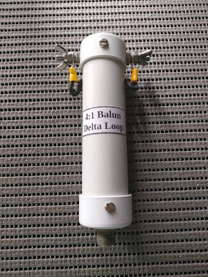
Build you own 4:1 Balun for a Delta Loop Antenna


I recently decided to build a Delta Loop Antenna for 10 meters but  if  a  20 meter version would fit into my yard then I will build the 20 meter version.  Why a 20 meter version?  Well this band carries most of the amateur radio DX traffic and it will also allow me to use it for other bands below 20 meters but then I need to use an antenna tuner.  To match the antenna for 20 meters I decided to build a 4:1 Balun.  Now there is quite a few methods to build the 4:1 Balun.  I decided to build the air-cored version which does not use a toroid but just a piece of pipe and some wire.  Please note the version I describe hear is for low power QRP use for up to 20 watts.  If you would like to build a 4:1  one hundred watt or higher Balun, just use thicker wire that are able to handle the power you will run.  For this topic I will not discuss the build of the Delta Loop Antenna in itself.  This will be done in a separate posting to follow soon.  Let's get cracking!

Here is your list of materials:

  1.  22 - 30 mm of PVC pipe. 120mm in length  I used 22 mm water pipe as this is all I had
  2.  2 x Electrical Lugs
  3.  1 x SO239 Connector 
  4.  2 x Stainless Steel Bolts and Nuts to install SO239
  5.  2 x Stainless Steel Bolts and Lock Nuts to connect the lugs to
  6.  2 x Stainless Steel Bolts and Nuts to connect the lugs to
  7.  2 x Stainless Steel Wingnuts to connect the lugs to
  8.  1 x 40 mm PVC pipe to cover the balun
  9.  2 x 40mm PVC End Caps to cover the balun
  10.  4 x Stainless Steel Self tapping Screws 12mm long
  11.  2 Pieces of heat shrink tubing to cover the two wires that comes out of the PVC cover.
  12.  Hot glue Gun + Hot glue
  13.  Marine Aqua 
  14.  1 x Small Electrical Lug to connect ground to SO239 connector.
  15.  1.2 meter of electrical red and black twin flex wire.  Wind 16 turns on 22 - 30mm PVC pipe.

I am not going to describe how to build this balun as the diagram and images explain everything in detail.  (Click on images for larger view.)


Finally seal all openings were water can get in like the End Caps,  the side holes were connections were made,  SO239, self tapping screws and bolts and nuts.  When finished you will have a 4:1 balun that will cost you under R100.00.  I will give an overview of the working of this balun as soon as I can put it to a test. Stay tuned!


Saturday, April 23, 2022

Notification: The 2022 SARL AGM will be live streamed on the ZS-LINK Network at 10h00 today!!


This years virtual SARL AGM will be live streamed on the ZS-Link Network at 10h00 this morning.  Please note that only certain items on the agenda will be lived streamed as the audio is received from the SARL.

You can access the Net as follow:

  • Echolink - Connect to ZS1I-L, ZS1FC-L, ZS3KBY-R or ZS5PMB-R  Please note if the last 3 stations is not connected to ZS1I-L then you need to connect to ZS1I-L for the NSN Net.
  • AllStar - Connect to node 49355
  • VHF - 145.550 Mhz Simplex in the Mossel Bay area.  Remember the 88.5 khz CTCSS tone
  • Any other Echolink, AllStar repeater or link station that is connected to either ZS1I-L or node 49355
  • Use of your cellphone by installing Echolink on your phone
  • By means of a Network Radio example Enrico TM8 etc.
  • Please feel free to join us on the ZS-Link Network for this event!!

    Enjoy!!


    NEW!! ICOM SHF Microwave Project for the 2.4 GHz & 5.6 GHz bands


    In 2021, ICOM announced that they were developing a transceiver for the microwave bands. At the time, it seemed like a highly unusual but welcome development.

    In April of 2022, they announced more details. They write... "Under the theme of “ICOM SHF Project – Super High Frequency Band Challenge –”, we started to develop a new amateur radio available for use in the 2.4 G

    Icom engineers are working hard to research and develop a number of never cleared challenges within the SHF band, such as large cable loss and higher frequency stability requirements. The ultimate goal is to bring it to the market as a new radio product. Icom is striving to bring to you a new era in fun and possibilities of an SHF band amateur radio, which to date has had high technical and equipment hurdles to overcome, and we hope to make these bands more attractive and active so that anyone can easily operate on them. We are developing an epoch-making SHF band amateur radio that no one has never imagined before."

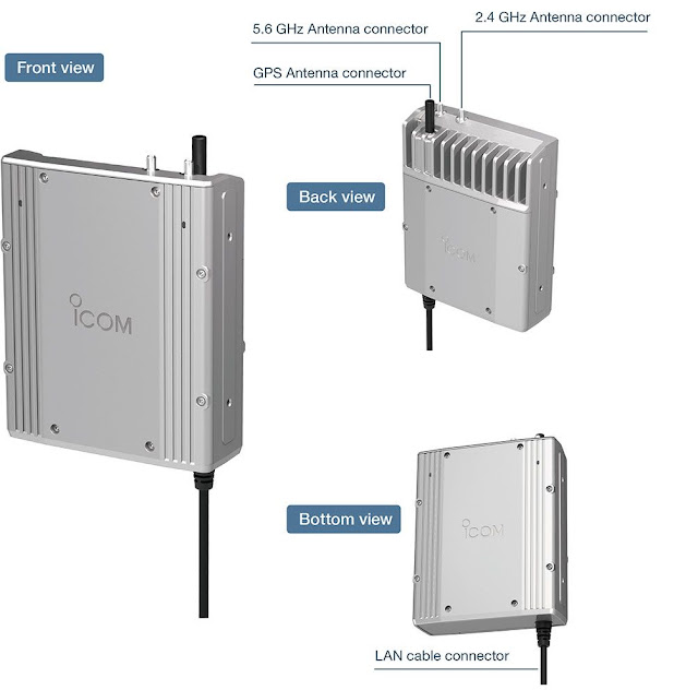
    The microwave radio is essentially a box that this designed to be fitted at the top of a mast or roof of a house. This will keep any coax losses to an absolute minimum.

    There are two SMA connectors on the top of the unit for antennas for 2.4 GHz and 5.6 GHz.

    The unit also has a GPS antenna. This will be used to achieve frequency stability which would be very difficult otherwise.


    ICOM write... "When installing the RF module directly under the antenna, the issue of how to supply DC power arises. Therefore, we decided to adopt PoE (Power over Ethernet) technology that supplies power over a LAN cable. Since Ethernet twisted pair wiring is limited to 100 meters, it is possible to install the RF module at a location 100 meters away from your shack (the controller). By adopting PoE technology, the connection can be made with a single cable, and the RF module can be installed more freely.

    Moreover, the PoE technology makes it possible to supply power with low power loss. Normally, if the power cable is extended to 20 meters, the voltage drop will be too large for a 10 watt transceiver, and it will not operate properly. With PoE technology, DC power loss can be reduced by raising the voltage and reducing the current, so it is possible to supply stable power, even if the cable is long."


    Notes & Comments:

    1) Power?? They don't say. If ICOM are talking about overcoming DC power losses then I think it suggests that the power is in the 'watts' range rather than say 50 to 100 milliwatts. I suspect it may well be a few watts and less than 10 watts.

    2) Why 2.4 GHz and 5.6 GHz?? Why not the 1.2 GHz (23cms) band where the losses are lower? I suspect it's because 2.4 GHz and 5.6 GHz are popular bands for WiFi and drones. There is already a lot of commercial antennas and equipment available for these bands and it makes sense to avail of it.

    It's also not hard to imagine some demand in Europe for use of this unit as part of a transmission setup to the QO-100 geostationary satellite which has an uplink on 2.4 GHz and downlink on 10 GHz.

    The 1.2 GHz band is also under pressure from commercial interests and I'd think companies would think twice before developing equipment for a band where permission might be withdrawn in the future.

    3) Controller... This is based on the IC-705 radio and it's likely to use a lot of the same components and parts. This not only reduces costs in terms of parts but a lot of the work in terms of software and user interface is already done.

    4) Cost?? On the subject of cost, I suspect this unit is certainly going to be expensive. ICOM gear isn't noted for being cheap anyway and I'd expect this unit will cost about the same as an IC-705 i.e. €1500 / $1500. We'll have to wait and see.

    No matter what the price is and what people think, this is very much a niche product and certainly not a money spinner for ICOM.

    5) Modes?? I'm sure the first thing people will think of are modes like FM, SSB and CW. As an ICOM product, I'd be surprised if it didn't support D-Star. But what about wide band data modes? Will this unit be used for data links and not just for weak signal work? Could it be part of an amateur radio microwave data network and not just a basic radio for basic two way communications?

    In conclusion: This is a very welcome development by ICOM and it has the potential to introduce a lot of people to the microwave bands. It really is a big deal to have one of the main amateur radio manufacturers making equipment for these bands.

    There is the potential that if ICOM sell enough of these units then they might encourage others to make some accessories or other related equipment. These units act as a seed and might encourage a lot more activity on these microwave bands.

    While it's likely that most interest is going to be in areas where there is a high concentration of radio amateurs, it will be interesting to see how this project develops.

    Addendum: The prototype model will be displayed at the Dayton Hamvention in Ohio, USA from 20th May 2022.

    ICOM SHF Microwave Project Website with PDF downloadable files.  Click HERE

    Source:  ICOM JAPAN and John EI7GL

    ED:  A very good friend Mike Bosch ZS2FM (SK) once said to me that the future of amateur radio lies in the GHZ bands!  I fully agree with him!!  - ZS1I


    New Amateur Radio Repeater Technology in the Southern Cape

    New amateur radio repeater technology soon available in the Southern Cape on the "AasvoĆ«lkop" Repeater Site.  There is great excit...