I was recently looking at a cheap USB Sound Card Radio Interface to use with:
- Baofeng Handheld Radio
- APRS Digipeater and Igate
- Winlink via FM Vhf using ARDOP
- Testing different digital modes on VHF/UHF
- Work the ISS using APRS Packet Digipeater
Prerequisites:
- Simplicity (using of modules)
- Use of a external USB Soundcard Dongle (SYBA)
- Needed adjustable speaker audio level to match the mic input
- FT232 compatible to convert to USB plug and play.
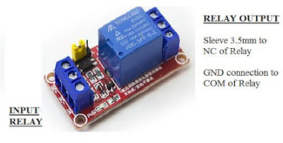
- Reliable switching between TX and RX (5v Relay Module)
- Transmit audio level circuit needed good audio isolation (1:1 Audio Transformer)
- Needed fast PTT switching for ARDOP
- Reduced audio sensitivity to ensure reliable reception of data via the Baofeng
- Weight and size was compromised due to using modules. With my bad eyesight it was fairly easy to join all the modules together without to much effort.
Components:
- R1 = 1K 1/4 watt
- R2 = 1K Pot
- R3 = 82K 1/4 watt
- TRF = 1:1
- C1 = 0.1uF Electrolytic
- 2 x 3.5 mm Stereo Jack Plugs
- 2m Audio Cable
- 1 x Speaker/Mic cable
- 1 x Veroboard
- 1 x FT232 Module (Red)
- 1 x 5v Relay Module
- 1 x USB Cable for FT232 Module
- 1 x Sound Card Dongle
Building/Construction:
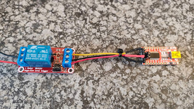
I am not going to go into detail as the images underneath provide more than enough information to successfully construct this interface.
Setup / Working:
The 1:1 audio isolation transformer isolate the Baofeng 3.5 mm sleeve from ground to enable the PTT circuit to work. Resistors R1 and R2 are used to attenuate the transmit audio level so that the deviation of the transmitted signal is ~ 3 kHz for a 1200 baud packet signal at maximum speaker gain on the soundcard. Careful initial tuning of the deviation by setting R2 is required in order for your signals to be reliably copied by others.
When the serial port RTS line goes high, the relay turns on shorting the sleeve of the 3.5 mm Baofeng connector to ground and asserting PTT on the radio. Simple as that.....but do not short the outputs and the Input as you will experience the well know smell and observe smoke escaping. This can also damage your radio!!!!
The receive audio circuit includes capacitor C1 to block any DC voltage from the soundcard. Resistor R4 is chosen to attenuate the audio signal from the Baofeng speaker (2.5 mm connector) to a level compatible with the soundcard microphone input. Assuming a typical soundcard microphone input impedance of 15 k Ohms, a value of 82 k Ohms attenuates the voltage by a factor of a approximately 6.5 (or 16.25 dB). Using this value of R4, together with a soundcard mic gain setting of between 7 and 10 on the computer. Reliable reception with the Baofeng audio knob set anywhere between the 6 and 9 o’clock positions.
The soundcard interface works well with the 1200 baud packet radio and ARDOP protocols. For the TNC, I use Sound Modem and ardopc by G8BPQ for ARDOP. I also tested the interface with MMSSTV and it works great. This interface could also be used with a hardware packet TNC.
Finally: Please note that this unit is specifically built for the Baofeng Radios. I have not tested it on any other cheap or more expensive handhelds. I have build many Sound Card Interfaces in the past and using my experience to build this interface. If we talk sound card interfaces then there is not only one or two designs available out there. I would however like to thank Dave K0RX and Charlie ZL2CTM as I used both their posts to create this Baofeng Sound Card.
In Part 2 I will provide more info on the practical working and images of the final installation of the modules in a cabinet.
Images: Click on images for larger view.


