Showing posts sorted by relevance for query Soundcard Interface. Sort by date Show all posts

Sunday, March 10, 2024

Revisit the ZS1I Soundcard Interface circa 2007 for Echolink today (Part 1)


Now why on earth would one go back to a ZS1I  Soundcard Interface that was designed in 2007.  One could say it is nostalgia but there is a very good reason to once again use one of the simple serial soundcard interface today.  Firstly the ZS1I Soundcard Interfaces work and they are reliable but apart from using them for digital modes it can also be used for VOIP and in this case I am going to use it as a Sysop RF Radio Linking Interface using Echolink to assist newcomers in setting up remote or normal connections to a repeater.  Hopefully I will also be successful in altering the Echolink settings to minimize or prevent the "Ping Pong" effect and also in reducing the latency experience as well as other hick-ups when using Echolink on the GRHub Network.  This topic will be divided into two parts.  In the first part we will be learning about soundcard interfaces and also looking at the ZS1I Soundcard Interface II and how to setup the interface to work digital modes. In the second part we will be looking at the ZS1I Budget Soundcard Interface that I will be using to hopefully curb the issues mentioned supra.  In part three I will be looking at a redesigned ZS1I Budget Echolink Interface Kit.

DOWN MEMORY LANE:  ZS1I SOUNDCARD INTERFACE II PROJECT 

INTERESTED IN DIGITAL MODES?……READ ON!

TNC's and Modems ruled the world of digital communications until recently. With the advent of high speed computing and digital signal processing (DSP) all this has changed. If you own a home computer (PC) with a sound card, all you need to do is download software and obtain an interface between the PC and your radio.

Soundcard interfaces are not data controllers, TNCs, decoders or signal processors. A good Soundcard Interface minimize computer noise entering the sensitive radio section,  while isolating DC and AC paths of the audio generated to and from the soundcard.

They merely:
· Couple audio from the radio receiver to the computer sound input.
· Couple computer-generated audio from the soundcard output to the radio transmitter.
· Provide some way for the computer to key the transmitter (PTT)


Due to lack of locally available interfaces in the past many radio amateurs imported them for large sums of money. No longer necessary……….the ready build ZS1I SOUNDCARD INTERFACE was locally available at a very reasonable price. This project is used extensively in the Southern Cape Region by Gizmo Amateur Radio Forum members. Some radio amateurs might consider this project to be simple and straightforward without the necessary bells and whistles. You're right.....that was the intention when I planned this project. Something simple but yet effective. I am not going to discuss the working of the soundcard here as the Internet is “infested” with information regarding the working of soundcard interface projects. I have used this soundcard effectively with various digital modes, even in contests. If you want a no fuzz no frill interface that delivers, than this one is for you.

IMPORTANT:

PLEASE NOTE THAT YOU WILL HAVE TO BUY A MICROPHONE CONNECTOR FOR THE SPECIFIC RADIO YOU INTEND USING. THE PTT/MIC AUDIO LINE IS MARKED ON THE SCREENED CABLE AND MUST BE SOLDERED AS ILLUSTRATED IN YOUR RADIO’S INSTRUCTION HANDBOOK.

There are a number of interfaces on the market, listed in ads in Amateur Radio Magazines and on the Internet. The recommended unit however to use is the “ZS1I Soundcard Interface”. This Soundcard Interface is available already assembled and tested,  from ZS1I ELECTRONIC PROJECTS at a substantial saving. (Unfortunately not available anymore.)

There are several reasons why you should use the ZS1I SOUNDCARD INTERFACE II.  While using a simple patch cord between the mic/speaker
connections will work, there are many reasons why this is not desirable or even safe for your computer and radio.

  1.  RF isolation - Nothing will kill your computer faster.
  2.  This interface has a keying circuit built in.
  3.  Many sound cards have 5 volts DC on the output, not good for your mic jack.
  4.  This interface has level controls built in, set 'em and forget 'em.
  5.  The interface provides isolation for all signal paths.
  6.  This interface do not use the VOX function to avoid embarrassing situations.
  7.  This interface has positive control of the transmit function.
  8.  This interface works with all operating systems. ( As long as your operating system has good software and soundcards, serial port support, the interface             couldn't care less which operating system you prefer.)
  9.  This interface is equipment independent and will work with almost all radios.
10.  This interface will give you hours of pleasure in working digital modes successfully.  

The ZS1I SOUNDCARD INTERFACE II has been tested successfully with the following software:

DIGIPAN, HAMSCOPE, HELLESCHREIBER, ECHOLINK, UIVIEW, WINPACK, AGW, MMSSTV, MMTTY, MIXW, STREAM, WINPSK, WIN WARBLE, WSJT, WIN APRSM, CWGET, AGW TRACKER, DTMF, ECHOSTATION, HAMDREAM, HAMSCOPE, MT63, SPECTRAN AND
W95SSTV.


I am sure that there is room for improvement but the intention with this project is to make a soundcard interface available to radio amateurs who wish to work digital modes.  I do not claim originality for the design of this project.  The writing of manuals, articles, drawing of the schematic diagrams, new layout of the printed circuit board, list of components and photographs were however compiled by ZS1I.  

COMMENTS ABOUT THE ZS1I SOUNDCARD INTERFACE II:

Eddie ZS6BNE writes:  
I must compliment you on your digital modes sound card interface!

I wired it up to my Icom 706 mkiig and initially could not get any signal from the rig to the PC. Connecting a COM port cable powered the unit and it works great! (No separate power supply nescessary) Clean signal to the PC's sound card and a clean signal from the PC to the rig and thus a clean transmitted signal.

Well done!

Nico ZS4N and Stephan ZS3S:

Successfully connected the ZS1I SOUNDCARD INTERFACE to Stephan's Kenwood TS2000 during the past week. Several Digital Modes and stations were worked without any problems and from reports received we had a "blast" on the HF bands working digital modes.

Johan ZS2I:

Johan is using a Yaesu FT1000MP with the ZS1I SOUNDCARD INTERFACE and is currently working PSK31 DX around the Globe.  The Souncard Interface needed a small modification as Johan wanted to use theDVS-2 connector of the Yaesu FT1000MP instead of the microphone connector.  


Now lets look at how to setup the ZS1I Soundcard Interface II.  To prevent a long posting I have decided to compile a PDF file that explain the setup of this interface.  However this setup and test manual can today still be used to test and setup other Soundcard Interfaces.  

Download: ZS1I SOUNDCARD INTERFACE II SETUP AND TEST MANUAL (PDF)

Finally:  In part two I will be looking at how to use the ZS1I Budget Soundcard Interface today in setting up Echolink using an RF Link Radio. (ZS1I-L)  If the experiments and tests are successful I will consider to make a redesigned ZS1I Budget Echolink Interface Kit available.  More on this in a future posting.

Tuesday, June 17, 2025

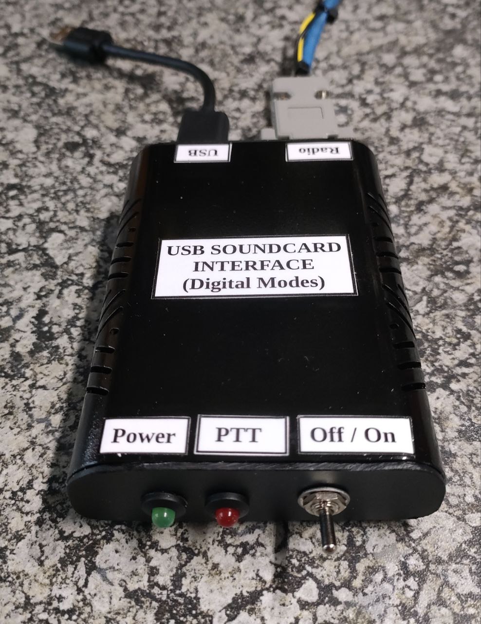
Let's build a KISS USB Soundcard Interface for Digital Modes (Part 1)


Through the years I have build many types of Soundcard Interfaces.  Some KISS models and others with micro controllers.  You can find some of the interfaces HERE. They all enabled me and many others to work various digital modes.  Nowadays many of the new radios do not need the conventional soundcard interface to allow you to work digital modes.  Several years ago I found The USBLink design by Julian Moss G4ILO  now SK.  I kept a copy of his article on my Soundcard Interface file for many years long before Julian went silent key.  About two weeks ago I paged through my file and found the article.  Now I do have several types of Soundcard Interfaces in my shack but this interface article gave me an idea that I will discuss in Part 2.  First off I need to build the USBLink Interface and test it live on the air.   The article of the USBLink is available HERE.  

This interface is in my opinion a KISS unit with no bells and whistles.  Herewith a few features that makes the unit a KISS interface:

1.  No Serial to USB interface / cable needed to handle PTT.

2.  No 1 : 1 (600 ohm) isolation transformers needed.

3.  Relatively low cost to construct the unit.

4.  Relatively small size compared to other homebrew interfaces. (Ideal for portable operation.)

5.  Does not use opto-isolation of the PTT line. (Not needed)

6.  Inexpensive USB Sound Card can be used. (Chinese cheapies will also work but I would rather buy a better quality product.)

7.  Project can be constructed on a piece of veroboard.

8.  No dedicated power supply needed for the Soundcard Interface.

9.  Diodes added for PTT transistor and radio protection. (I would however add another switch to cut off the PTT line going to the transceiver to prevent accidental PTT activation when unit is left unattended.)

10.  Plug and Play Unit - No drivers to install.

Finally:  This is a simple low cost circuit which works well and allows you to operate sound card digital modes without tying up your computer's built-in sound card.  I constructed this interface and tested the interface on VHF.  In part 2 I will provide feedback on how the interface behave on HF but from what I observed using a VHF transceiver it should work just as well on HF.  Although I am not in favor of using VOX in any way in amateur radio, I do not foresee any issues using this interface attended.  I would not leave this interface unattended and therefor suggested the additional switch  between ground and PTT to prevent accidental transmissions.

Images:  (Click on images for larger view.)


Monday, May 19, 2025

How I setup my Yaesu FT817 Radio and Homebrew Arduino Soundcard Interface (SignalLink Clone) to work Digital Modes


During the PEARS VHF/UHF Contest that took place in January 2025 I decided to setup my trusted Yaesu FT 817 Radio using my Homebrew  Arduino Soundcard Interface to work a few digital mode stations.  In a previous article available HERE I explained another type of homebrew interface that includes the CAT control.

The Arduino Soundcard Interface I am going to describe can be used with many types of radios.  This interface function the same as the commercial available SignalLink Interface, therefor the reason that it is called a SignalLink Clone.

The FT817, 857 and 897 radios have a few settings that must be setup correctly,  if not then you will not be able to play with digital modes.

Please take note that the setup explained worked for me. 

My Setup:  ( Yours might differ depending on the equipment you use)

Setting up the Computer and Software:

DO NOT switch the Yaesu FT817 or the computer ON.  
We first need to plug in all the cables.
Plug the USB cable coming from the Soundcard Interface into a USB port on the computer.
Plug the FT817 Mic Cable coming from the Soundcard Interface into the mic socket of the FT817
Plug the 3.5 mm Extension plug into the SP Ext. Socket on the FT817
The switch next to the 3.5 mm socket must be set to SP = Speaker
Plug antenna and radio power cord in
Ensure the correct antenna port is selected.  Either front or rear.  (Menu #7)
Now power up the computer and the FT817 Radio
Radio and Interface should now be ON
Set frequency on radio.  In this case we start with VHF and FT8 = 144.174 MHz USB
Now start the WSJT-X Program 

WSJT-X Setup:

Go to file settings - Radio
CAT must be OFF if you not going to use CAT = Rig:  NONE
PTT Method = VOX
Click on Audio TAB

Soundcard:

Input:  Microphone (32-USB PNP Sound Device)
Output:  Speakers (32-USB PNP Sound Device)
Input = Mono
Output = Mono
Click OK

In WSJT-X:

Monitor Button should be green and  O next to the band should also be green.  Radio and WSJT-X are talking to each other.  If not then check Hardware and Sound.
Control Panel =  Hardware and Sound.  Select Manage Audio Devices in Windows computer
New window will open named:  Sound with playback displayed
Double click on Speakers
Speaker Properties will open
Go to Levels

Speakers 98 Balance
Microphone 68

Click OK

Go to Recording TAB
Double click Microphone
Microphone Properties will open
Go custom. AGC must not be selected
Go to Levels

Microphone 50
Click OK

All other Playback and Recording devices must be DISABLED!
Voicemeeter Banana must not run at all if you have it installed!

That should be it for the computer audio settings.

Now for the Yaesu FT817 Radio Setup:

Press F for more than 2 seconds
We are now in the MENU of the FT817
Rotate teh SEL knob on radio (left side) to select menu 1 - 57

Setup the following MENUS for the Arduino Soundcard Interface as follows:

# 3  9600 Mic = 50
# 7  Antenna = Front or Rear
#14  Cat Rate = 9600  (If used)
#24  Dig Disp = 0 hz
#25  Dig Mic = 70
#26  Dig Mode = user-u
#27  Dig Shift = 0 hz
#29  FM Mic = 50
#38  OP Filter =  OFF (CW or SSB Filter)
#39  PKT Mic = 50
#40  PKT Rate = 1200
#45  SQL/RF-G = SQL (VHF) (RF Gain for HF)
#46  SSB Mic = 50
#51  Vox Gain = 50 (If used)
#52  Extend = ON
 
MODE =VHF/UHF = FT8 144.174 Mhz USB (USB work in VHF)
To check if equipment is setup correctly we are going to use an SDR Receiver Dongle installed on another computer.  Start the SDR computer with the RTL plugged into a USB port.  Open OpenWegRX program.  Once open select RTL-DDR 2m Voice Repeaters.  The 2m band will be displayed.  If you can hear white noise and signal meter works, go back to the computer with WSJT on it.  Click on the Tune button in WSJT-X.  Radio should TX and a line will appear on the window (waterfall)  Move the yellow ^ marker exactly on the line in the waterfall.  You will hear the tune signal clearly and your RX bar will go to red.  This means you are on the frequency of your radio that is in TX mode.  Stop Tune.
Select USB in Modes and click on the down arrow.
 
Select FT8 and two screens will open while DIG in the modes will turn yellow.  On screen = waterfall and other display station info.   Now enable TX on WSJT-X using FT8.  You should hear FT8 clearly in OpenWebRX.  Decode box in OpenWebRX will display CQ info:
 
UTC               dB    DT        Freq       Message
 
08:58:00         1      0.2     144.175    CQ ZS1I KF15
 
That's it your TX signal is now going out on the airwaves and being received by OpenWebRX
 
You are now ready to make your first QSO on VHF with the Yaesu FT817 Radio and the Arduino Soundcard Interface.
 
As said previously the above settings worked for my setup.  Your setup might differ but I am sure that some of the information in this article will be useful in setting up your Yaesu FT817, 857 or 897 radio to work digital modes.
 
You should now be able to work digital modes with the Yaesu FT817 Radio.  

Enjoy working digital modes in amateur radio!!           

General Checks and Settings:
 
1.  Set MTR ALC  Press F once, select MTR ALC by pressing B.  This will reflect ALC when in TX mode.
2.  Check antenna Input = Front or Rear  MENU =  #7  (Select socket where your antenna is plugged in.)
3.  Check SWR Meter (PWR and SWR)
4.  Check receiving meter (WSJT-X)  Must be in the green between 40 - 60 dB.  If in the red adjust recording level - microphone to a lower setting until meter is in the green.
5.  Add  Fan to the back o the Yaesu FT817 to prevent the radio from overheating.
6.  From time to time the FT817 screen will warn you of high SWR = SWR High.  If your antenna is tuned correctly check all other connections that they are tight.  Check also all patch leads for good connectivity.  Check if the radio is cutting power and if the warning comes up between voltage and mode.  You can also try to use the other antenna socket on the radio (Front or Rear)  This anomaly happens from time to time especially if the radio is moved around or used in portable mode.
7.  Never forget to have the FT817 Operating Manual in close proximity.  You will need it more than you think.
 
Images:  Click on images for larger view.
 
NOTE:  The Arduino Soundcard Interface needs an urgent facelift.  Hopefully I will find some time to re-spray and label it properly.


Wednesday, December 15, 2021

Young and New Radio Amateur accomplish his first VOIP/RF Link project successfully!!


Images: Icom radio used by Corne in establishing a link to the GRHub Network

Image: This is a great soundcard to use for VOIP. Ensure that it is not a clone but the original.

In an earlier post HERE  I described how Corne ZS1COR wanted to connect via ZS1I GRHub Network to the ZS2PE-R Network.  This time around Corne wanted to extend the coverage area of the  GRHub Network by installing a RF VHF/UHF Radio Link via Echolink in the George area.  Now I am sure that you all know this could be achieved quite easily by just adding a SignaLink interface between the computer and radio.  With the current price of this interface it is out of reach of many radio amateurs in South Africa.  Corne already had a homebrew USB Soundcard Interface for digital modes but this was only for digital modes and not for voice according to the constructor of the interface.

Image: ZS1I Mini Soundcard Interface donated to Corne ZS1COR.


I scratched around in my junk-box and found an old homebrew serial sound card interface that I developed and build many years ago.  It would be a long-shot but it must just work.  Corne arranged for the pickup and no sooner than he received it he indicated that he needed help to setup the interface.  When I still manufactured ZS1I Sound Card Interfaces for radio amateurs to purchase, I also compiled a setup manual that allow a person to successfully install all the necessary.  The manual and diagram was send to Corne via Telegram.  Corne could not wait and immediately started to setup the unit only to find that it stays in PTT mode, the reason unknown.  You could hear the disappointment in his voice. OM  Danie ZS1DBJ offered to help but they still could not get the unit to work.  I then suggested that Corne use the VOX of the Echolink program just for the interim until such time as a dedicated interface was constructed.

Now VOX is definitely not to be used on a permanent link to the GRHub Network or for that matter to any permanent connection to any VOIP Network.  I am sure I need not explain all the caveats of VOX.  Let just say it is unreliable, can cause havoc etc. etc.  The correct way would be to use a dedicated radio, soundcard fob and computer. The Echolink software needs to interface to the radio in order to control Push To Talk (PTT), recognize when a signal is present on the radio (COS) and also manage the TX & RX audio streams between the computer and the radio. All of these functions are achieved using a USB sound card fob that plug into to the computer's USB connectors . The connections to the radio however require wired connections.

As you might expect the RX & TX audio are already part of the sound card as this is the intended function of a sound card. RX audio goes to the Microphone input and the TX audio comes from the sound output  The sound card chip inside the fob has some extra GPIO abilities that we need to tap into for PTT (Push to talk) signaling and COS (COS – “Carrier Operated Signal”, “Carrier Operated Squelch” or “Carrier Operated Switch” or COR Carrier Operated Relay… all the same thing, just different names). Between the fob and the radio some simple addition circuitry is needed.  Here is an image of the soundcard fob that I constructed and currently use with the ZS1I AllStar node.

Image: Heavy modified Syba UCM119 Souncard as used with the GRHub Network

Various commercial soundcard fobs are available from overseas suppliers but as I already stated are rather expensive to import.  The above unit is really fail safe and works great.   The USB Soundcard was imported for R143.00 per unit.  The soundcard is called a Syba UCM119.  Enough about sound fobs.  

Let get back to Rocking n Rolling!  Yes, we had a great session of Rocking n Rolling on the GRHub Network starting 11 December 2021 in the afternoon and ending on the 12 December 2021 early evening.  What is this rocking and rolling about?  Well it sounded like rock and roll on the network as Corne ZS1COR was experimenting in setting up a VHF/UHF RF Link via Echolink to the GRHub.  After literally spending the whole of Saturday afternoon and evening trying different settings and getting advice from yours truly but the end result on the 11 December 2021 was not good. 

Unfortunately he could only "play" with VOX in getting the link to work.  After some tests on the VHF band it was established that interference in George was so bad at his QTH that VHF was unusable.  It resulted in all sorts of rock and roll sounds combined with his voice audio.  One should remember that Corne is fairly new to amateur radio and that he did all the tests, settings and experimenting alone in his shack. He tried several options but to no avail.  Bad audio and lots of rock and roll sounds was heard on the network.

Sunday started of with the same bad audio and rock n roll sounds.  No improvement after trying several connections and settings. Just after 16h00 Corne decided to give UHF a try as he discovered that there was no interference on UHF at his QTH.  He used 435.400 Mhz and it was not long before clear audio was heard with no "rock and roll" sounds.  The "rock and roll" changed to great amateur radio audio. Now one should remember that settings had to be made on Echolink, RF Radio, Laptop Computer and the Soundcard Interface to ensure that all the equipment "plays ball" to enable clear good audio. 


Image:  GRHub Network connection log for the past Saturday and Sunday

Corne was once again "on fire" but he wanted to test with radio amateurs in George.  It was not long before Michael ZS1MMB and Keverne ZS1ABU joined Corne while yours truly monitored the GRHub Network to listen on all the nodes and links for good audio quality.  I can confirm that great audio was forthcoming from all three radio amateurs in George.  They chatted away for a lengthy period about how Corne successfully established a new GRHub Network RF and Echolink link.  Quite a few questions were forthcoming and answered.  I for one was very happy with the quality of audio forthcoming from all participating stations but as already stated this setup should not be used for a permanent link setup.

All talks ceased early evening after a long and tiresome weekend of testing, disappointment and finally success and excitement.  I would like to thank Michael and Keverne for assisting Corne in testing his link setup.  I was able to evaluate the link audio and other connections on the GRHub while the three of them were chatting.  It was clear that everybody had a "ball of a time".

Once again the "bull fighter" was hard at work and it resulted in a great and successful "fight".

I want to congratulate Corne ZS1COR in succeeding in setting up a temporary link from George to the GRHub Network, Mossel Bay for use by radio amateurs in the George area. 

VOX is not ideal for a permanent connection to the GRHub Network but it can be used as a free standing option with supervision.  After the festive season we will be looking at setting up a fairly fail safe link connection to and from George.

Stay tuned!!


Sunday, September 3, 2023

DIY Soundcard Interface for the Baofeng Handheld Radio. (Part 1)


I was recently looking at a cheap USB Sound Card Radio Interface to use with:

  • Baofeng Handheld Radio
  • APRS Digipeater and Igate 
  • Winlink via FM Vhf using ARDOP
  • Testing different digital modes on VHF/UHF
  • Work the ISS using APRS Packet Digipeater

Prerequisites:

  • Simplicity (using of modules)
  • Use of a external USB Soundcard Dongle (SYBA)
  • Needed adjustable speaker audio level to match the mic input
  • FT232 compatible to convert to USB plug and play.
  • Reliable switching between TX and RX (5v Relay Module)
  • Transmit audio level circuit needed good audio isolation (1:1 Audio Transformer)
  • Needed fast PTT switching for ARDOP
  • Reduced audio sensitivity to ensure reliable reception of data via the Baofeng
  • Weight and size was compromised due to using modules.  With my bad eyesight it was fairly easy to join all the modules together without to much effort. 

Components:

  • R1 = 1K 1/4 watt
  • R2 = 1K Pot
  • R3 = 82K 1/4 watt
  • TRF = 1:1
  • C1 = 0.1uF Electrolytic 
  • 2 x 3.5 mm Stereo Jack Plugs
  • 2m Audio Cable
  • 1 x Speaker/Mic cable
  • 1 x Veroboard
  • 1 x FT232 Module (Red)
  • 1 x 5v Relay Module
  • 1 x USB Cable for FT232 Module
  • 1  x Sound Card Dongle

Building/Construction:

I am not going to go into detail as the images underneath provide more than enough information to successfully construct this interface.

Setup / Working:

The 1:1 audio isolation transformer isolate the Baofeng 3.5 mm sleeve from ground to enable the PTT circuit to work. Resistors R1 and R2 are used to attenuate the transmit audio level so that the deviation of the transmitted signal is ~ 3 kHz for a 1200 baud packet signal at maximum speaker gain on the soundcard. Careful initial tuning of the deviation by setting R2 is required in order for your signals to be reliably copied by others.

When the serial port RTS line goes high, the relay turns on shorting the sleeve of the 3.5 mm Baofeng connector to ground and asserting PTT on the radio.  Simple as that.....but do not short the outputs and the Input as you will experience the well know smell and observe smoke escaping.  This can also damage your radio!!!!

The receive audio circuit includes capacitor C1 to block any DC voltage from the soundcard. Resistor R4 is chosen to attenuate the audio signal from the Baofeng speaker (2.5 mm connector) to a level compatible with the soundcard microphone input. Assuming a typical soundcard microphone input impedance of 15 k Ohms, a value of 82 k Ohms attenuates the voltage by a factor of a approximately 6.5 (or 16.25 dB). Using this value of R4, together with a soundcard mic gain setting of between 7 and 10 on the computer.  Reliable reception with the Baofeng audio knob set anywhere between the 6 and 9 o’clock positions.

The soundcard interface works well with the 1200 baud packet radio and ARDOP protocols. For the TNC, I use Sound Modem and ardopc by G8BPQ for ARDOP. I also tested the interface with MMSSTV and it works great.  This interface could also be used with a hardware packet TNC.

Finally:  Please note that this unit is specifically built for the Baofeng Radios.  I have not tested it on any other cheap or more expensive handhelds.  I have build many Sound Card Interfaces in the past and using my experience to build this interface.  If we talk sound card interfaces then there is not only one or two designs available out there.  I would however like to thank Dave K0RX and Charlie ZL2CTM as I used both their posts to create this Baofeng Sound Card.

In Part 2 I will provide more info on the practical working and images of the final installation of the modules in a cabinet.

Images:  Click on images for larger view.


Monday, March 3, 2025

How I setup my Yaesu FT817 Radio and Homebrew Soundcard Interface to work Digital Modes

Image:  ZS1I Yaesu FT817 Radio

Image:  ZS1I Homebrew Yaesu FT817 Soundcard Interface

During the PEARS VHF/UHF Contest that took place in January 2025 I decided to setup my trusted Yaesu FT 817 Radio using my homebrew soundcard interface to work a few digital mode stations.  The FT817, 857 and 897 radios have a few settings that must be setup correctly,  if not then you will not be able to play with digital modes.

Please take note that the setup explained worked for me.  I did not use the CAT on this occasion as I need to buy the necessary accessory plug before I can use CAT. 

My Setup:  ( Yours might differ depending on the equipment you use)

Setting up the Computer and Software:

DO NOT switch the Yaesu FT817 or the computer ON.  
We first need to plug in all the cables.
Plug the USB cable coming from the Soundcard Interface into a USB port on the computer.
Plug the data cable coming from the Soundcard Interface into the Data socket of the Yaesu FT817. (Back of the radio.)
Now we can switch the radio on and then the computer.
The radio, computer and interface will now be be ON.
Start WSJT-X by clicking on the icon in your desktop or program start menu.
Go to File and then click on Settings then Radio.
CAT must be OFF  -  Rig = NONE
PTT Method = DTR Port:  Com3
Next click on Audio 
Here we will setup the Soundcard to be used

Soundcard:

Input:  Microphone (19-USB Headphone Set)  -  Left
Output: Speakers (19-USB Headphone Set)  -  Both

Click OK

Monitor Button should be green and round   0 should be green.  Radio and WSJT-X are now talking to each other.  If not check your hardware and sound on the computer.

Select:  Go to Control Panel. Click  on Hardware and Sound and then on Manage Audio Devices.  Sound window will open with Playback displayed.  Note: If you do not use VoiceMeeter then ignore those settings.

Playback:

Speakers:  19-USB Headphone -  Ready
Speakers:  Behringer USB - Disabled
VoiceMeeter Aux Input - Default Device

All others disabled

Recording:

Microphone: 19-USB Headphone - Ready
Line In:  Behringer USB - Disabled
VoiceMeeter Aux Output - Default Device

All others disabled

Managing Devices:

To set the level of the devices go back to Playback and double click on Speakers.  
Select Levels.  
 
Set levels as:

Speakers 83 
Main volume 83
 
To set the level of the devices go back to Recording and double click on Microphone (or Line In)  Select Levels.
 
Set levels as:
 
Microphone 82 
AGC MUST BE OFF!!

Go back to Playback
Select VoiceMeeter Aux Input (Double Click) 
Select Levels

Set levels as:
 
VoiceMeeter Aux Input = 100
Main Volume = 93
 
Click OK

Go to Recording and double click on Voice Meeter Aux Output
Select Levels

Set levels as:

VoiceMeeter Aux Output = 89
Wave in Volume = 100

Click OK

We completed the setup of sound on the computer.  Now we need to setup VoiceMeeter Banana

Open the VoiceMeeter program
 
Hardware Input 1 =  Behringer USB Audio
Hardware Out = Behringer USB Audio
 
Select the above if not displayed in VoiceMeeter.  Restart VoiceMeeter once selected.
 
Setting up WSJT-X Program:
 
I am not going to explain setting up the WSJT-X software as there is a complete manual explaining how to install and setup WSJT-X.  Please use the manual.

Setting up the Yaesu FT817 Radio to work digital modes:

Press F for more than 2 seconds
When in MENU rotate the SEL knob on radio to select menu 1 - 57
Set the following Menus:

# 3  9600 Mic = 50
# 7  Antenna = Front or Rear
#14  Cat Rate = 9600  (If used)
#24  Dig Disp = 0 hz
#25  Dig Mic = 70
#26  Dig Mode = user-u
#27  Dig Shift = 0 hz
#29  FM Mic = 50
#38  OP Filter =  OFF (CW or SSB Filter)
#39  PKT Mic = 50
#40  PKT Rate = 1200
#45  RF Gain/SQL = RF Gain (Digital)  SQL FM
#46  SSB Mic = 50
#51  Vox Gain = 50 (If used)
#52  Extend = ON
 
MODE =  DIG in SSB
             =  PKT in VHF/UHF

General Checks and Settings:
 
1.  Set MTR ALC  Press F once, select MTR ALC by pressing B.  This will reflect ALC when in TX mode.
2.  Check antenna Input = Front or Rear  MENU =  #7  (Select socket where your antenna is plugged in.)
3.  Check SWR Meter (PWR and SWR)
4.  Check receiving meter (WSJT-X)  Must be in the green between 40 - 60 dB.  If in the red adjust recording level - microphone to a lower setting until meter is in the green.
5.  Add  Fan to the back o the Yaesu FT817 to prevent the radio from overheating.

As said previously the above settings worked for my setup.  Your setup might differ but I am sure that some of the information in this article will be useful in setting up your Yaesu FT817, 857 or 897 radio to work digital modes.
 
You should now be able to work digital modes with the Yaesu FT817 Radio.  

Enjoy working digital modes in amateur radio!!
 
 
Images:  (Click on images for larger view.)


Closure of this ZS Link Network Blog - 29 April 2026

This will be the final posting on the ZS Link Network Blog. This blog will no longer be updated but will remain available for research an...