Article can be downloaded in PDF format by clicking HERE.
ZS5SAM - DMR Configuration Tutorial – TAIT EUD (Doc Ver 1.0.1)
This document will assist you in setting up a Tait based MMDVM repeater using the TM81xx series mobiles or TB7100 or TB8100 analogue repeater. I configured for the SP8NTH modem board.
I found that DMRDelay setting had to be adjusted from 30 to 45 after last software update so keep that in mind should you experience any RX decoding problems.
Preparing you Arduino Due & and uploading Modem Software
Download and install Arduino software – http://www.arduino.cc
Make mod changes ………..
Download .zip of latest MMDVM Modem Library - https://github.com/g4klx/MMDVM
Create folder called MMDVM in your Arduino Library folder on your PC and extract contents of .zip file into MMDVM folder.
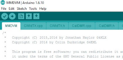
Double click on the MMDVM.ino file which will launch the Arduino application.
Click on the Config.h tab and uncomment :
// #define ARDUINO_DUE_NTH as well as // #define EXTERNAL_OSC 12000000, when using the NTH board with 12MHz external oscillator. Uncomment means removing the two “//” from both the relevant lines.
Ensure that // #define ARDUINO_DUE_ZUM_V10 has the // lines as is uncommented by default.
Latest version of Config.h files also sets parameters for wide C4FSK & RSSI.
Remember to read the BUILD.txt file and follow instructions before compiling your Arduino.
Note: Click on images for larger view.
Next click on Verify (Tick icon top left above tabs) to check and compile your sketch.
Once you see the “Done compiling” notification click on Upload (Right Arrow Icon) which will again compile your sketch and upload it to your Arduino Due.
If you get an error “unable to find Com Port” check under Tools/Serial Ports and ensure correct Com port was selected then try and upload again.
On completion you will get verification that upload was checked and successful.
Installing OS onto Raspberry Pi (Using Windows OS)
Format 8 GB or larger MicroSD as FAT32
Download latest Raspbian Lite zip file from https://www.raspberrypi.org/downloads/raspbian/
At time of document, Raspbian Jessie Lite was the latest version.
You can also access the online installation guide for multiple OS platforms here, https://www.raspberrypi.org/documentation/installation/installing-images/README.md
Extract the .img file, from the .zip file, into a folder on your hard drive
Launch Win32DiskImager software (as Administrtor), select Image file location as well as MicroSD Device location and write the image file to your MicroSD by clicking on the “Write” button.
On completion of the write you should get a “Write Successful” window. Click OK then eject your MicroSD device and insert the card into your Raspberry Pi, connect via LAN to your network and power up the device.
Raspberry Pi SSH Login without Monitor
Update: New builds of Raspbian now have SSH port 22 disabled by default, therefore you will have to enable it first by attaching a monitor and keyboard and running # sudo raspi-config
All you need connected to your Raspberry Pi is power and LAN connection.
DHCP is activated by default on the Raspberry Pi, thus you will be allocated an IP address by your router.
However keep in mind that the next time you power it up, the router may allocate a different IP address. Next we will scan the network to find the IP address of the Raspberry Pi
We can find out the IP address of the Raspberry Pi by logging into the router and seeing what devices are connected. However an easier way would be to use a tool such as Soft Perfect Network Scanner.
To connect via SSH, download the free program called putty. http://www.putty.org/
Launch putty and enter your IP address from the scanner. Putty defaults to using SSH so no other changes should be required.
You can save the setting for future use, however remember your IP address may change.
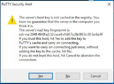
Click on Open. The first time you conect to the Raspberry Pi you will see a warning dialog. This is putty's way of making sure you trust the device you are connectiong to. Click on Yes and the settings will be saved for next time.
You should now have a terminal screen, and can log in using the default username of pi and password, raspberry.
Installing Host Software on Raspberry Pi with Raspbian Jessie Lite
Expand File System and Change Locale
# sudo raspi-config
Highlight option 1 (Expand File System) and tab to <Select> then Enter.
Next highlight Internationalisation Options and set your Locale details
On completion tab to <Finish> then press Enter.
Update/Upgrade OS and install the git application.
# sudo apt-get update
# sudo apt-get upgrade
# sudo apt-get clean
# sudo apt-get install git screen
# cd /opt
# sudo git clone https://github.com/g4klx/MMDVMHost.git
# sudo git clone https://github.com/g4klx/MMDVMCal.git
Build MMDVM Host Software
# cd /opt/MMDVMHost
# sudo make
# sudo nano MMDVM.ini
Here you can customize the ini file to your needs
Build MMDVM Calibration Tool
# cd /opt/MMDVMCal
# sudo make
Turn off Bluetooth on the Raspberry Pi3
The onboard Bluetooth clashes with the Modem and needs to be deactivated with the following command:
sudo bash -c 'echo "dtoverlay=pi3-disable-bt" >> /boot/config.txt'
This adds the dtoverlay=pi3-disable-bt to the bottom of the /boot/config.txt file.
You could alternately manually add this line to config.txt if you wish. Would be good idea to prepend the line with a comment e.g. # Mod to turn off Bluetooth.
Create Service (The text in red needs to be added and saved to file)
# sudo nano /lib/systemd/system/mmdvmhost.service
[Unit]
Description=MMDVM Host Service
After=syslog.target network.target
[Service]
User=root
WorkingDirectory=/opt/MMDVMHost
ExecStart=/usr/bin/screen -S MMDVMHost -D –m /opt/MMDVMHost/MMDVMHost /opt/MMDVMHost/MMDVM.ini
ExecStop=/usr/bin/screen -S MMDVMHost -X quit
[Install]
WantedBy=multi-user.target
# sudo chmod 755 /lib/systemd/system/mmdvmhost.service
Create a symbolic link between your script and a special location under /etc:
# sudo ln -s /lib/systemd/system/mmdvmhost.service /etc/systemd/system/mmdvmhost.service
Create Timer (The text in red needs to be added and saved to file)
# sudo nano /lib/systemd/system/mmdvmhost.timer
[Timer]
OnStartupSec=60
[Install]
WantedBy=multi-user.target
# sudo chmod 755 /lib/systemd/system/mmdvmhost.timer
Create a symbolic link between your script and a special location under /etc:
# sudo ln -s /lib/systemd/system/mmdvmhost.timer /etc/systemd/system/mmdvmhost.timer
Make systemd aware of your new service (This enables new service and activates the 60 sec timer)
# sudo systemctl daemon-reload
# sudo systemctl enable mmdvmhost.timer
# sudo reboot
Service should start 60 sec after bootup.
Some more usefull commands
Start Service manually
# sudo systemctl start mmdvmhost.service
Stop Service manually
# sudo systemctl start mmdvmhost.service
Restart Service manually
# sudo systemctl start mmdvmhost.service
Connect to Screen Output
# sudo screen -r MMDVMHost
Ctrl+a then d to disconnect from screen and keep the service running.
Run MMDVMHost
# sudo ./MMDVMHost MMDVM.ini
Run MMDVMCal
# sudo ./MMDVMCal /dev/ttyACM0
To update MMDVM App
# cd /opt/MMDVMHost
# sudo mv MMDVM.ini /opt/MMDVM.ini (move existing MMDVM.ini file to safe place)
# sudo git pull https://github.com/g4klx/MMDVMHost.git
# sudo make
To update CALIBRATE app follow above but of course be in the MMDVMCal directory and also point to MMDVMCal.git at repository.
Notes:
It is recommended supplying the Due with 5VDC at the micro USB socket. (2B recommend 1.2A and Model 3 recommend 2.5A)
Raspberry Pi – Commands
sudo apt-get update
sudo apt-get upgrade
sudo apt-get clean (Cleans out update Cache)
sudo rpi-update (Updates Pi Firmware)
Calibrating your Modem
TX Calibration
For TX Calibration, use a spectrum analyzer to observe the TX RF directly.
Launch the MMDVCal program (# sudo ./MMDVMCal / dev/ttyACM0) and select the DMR test 1.2kHz test tone.
Use MMDVMCal to switch the repeater to TX and generate the DMR Cal signal. (Space bar switches TX on/off)
While slowly turning the TX deviation pot on the Modem board observe the sidebands of the RF signal on the analyzer. When you have reached the correct deviation level, you will notice that the carrier in the center of the RF spectrum shows a clearly visible dip. This is the "Bessel zero" where the deviation of both tone sidebands "zero out" the carrier. Adjust the pot for maximum dip depth.
I found this null point to equate to about 2.9kHz Deviation using the MMDVMCal 1.2kHz test tone.
RX Calibration
Preset RX audio from receiver to -10dB @ 1kHz (1.5kHz wide) at the Modem header (SV2)
Next use an oscilloscope to check the incoming RX signal from the Modem board to the ADC pin (Pin A0) of the Arduino Due:
The Modem board should create a 1,65V DC offset (Half 3.3V) at the ADC input. Key your radio on a simplex channel and observe the audio on the ADC pin overlaying the DC offset. You can use the rising edge of the receiver’s RSSI signal for triggering the scope.
The RX pot on the modem board must be adjusted in a way that the peak amplitude of the audio signal neither reaches the zero or the 3.3V maximum. Keep a margin of 0.3 to 0.4V to both limits to be safe! Take care to ensure that the ADC input of the SAM3X is never overdriven by the audio signal. For a fine tuning you can adjust the TX / RX settings in the MMDVM.ini file
It is recommended supplying the Due with 9VDC at the 2.1mm DC socket and not relying on the 5VDC supplied via the USB port (250mA)
Notes when using external 12MHz FCXO
The frequency of the TCXO must be an integer multiple of 24000 and 48000
Frequencies such as 12.0 Mhz (24000 * 500) and 14.4 Mhz ( 24000 *600) are suitable.
Frequencies such as 10.0 Mhz (24000 * 416.666) or 20 Mhz (24000 * 833.333) are not suitable.
This can be configured in the Config.h file prior to the code being compiled and loaded into the Due.
To configure the code for your oscillator uncomment the relevent line in the Config.h file by deleting the // characters.
e.g. #define EXTERNAL_OSC 12500000
Next you need to ensure that the setting OscOffset = in your MMDVM.ini file is set to zero. This setting is only for used when calibrating the internal oscillator and not required when using an external clock. (IC4 is not required so simply jumper R2 & R26 with 0 Ohm resistors instead)
Also keep in mind that the NTH Modem board caters for HCMOS TCXO type and not the Clipped Sinewave type TCXO.
Tait T2000 mods for DMR
Receiver (RX)
Fit a DB9 connector to rear of radio in space provided.
Pins to use
S13-1 DET-AF-OUT to DB9 Pin 6 .166mV (-15.6dB) present
S13-11 OPTIONS GROUND to DB9 Pin 8
S14-3 BUSY to DB9 Pin 9 (BUSY is High + 5VDC in idle)
Transmitter (TX)
S13-11 OPTIONS GROUND to DB9 Pin 8
S14-6 PTT FROM OPTO to DB9 Pin 9 (Is High +5VDC in idle)
S13-8 TX-SIG-IN to DB9 Pin 6 .675mV (-3.5dB) present – Use 2.2uF Cap
The T2000 is not the ideal radio to use for DMR as frequency drift causes problems. Radio needs to be on for close on an hour before VFO is stable enough for DMR.
Tait TM8115 & TM8200 mods for DMR
Receiver (RX)
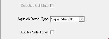
Under Basic Setting – Change Squelch Detect type to “Signal Strength” – This is NB!
Go to Programmable I/O – Digital Tab and change as follows:
Next go to Programmable I/O – Audio Tab and change as follows:
Save file and program these changes back to the radio.
Transmitter (TX)
Under PTT – Select the External PTT (1) Tab and change as follows:
Next go to Programmable I/O – Digital Tab and change as follows:
Next navigate to Programmable I/O – Audio Tab and change as follows:
Note: When inputting your frequencies remember to use 12.5kHz spacing
TM8115 Auxiliary Connector
The auxiliary connector is an 18 way two row right angled IDC (Insulated Displacement Connector)
On the Receiver (RX) we will be using the following Pins
Pin 1 AUX GP0I7 BUSY to Modem Pin 5 (Green)
Pin 6 RSSI to Modem Pin 6 (Purple)
Pin 13 AUD TAP OUT RX Aud to Modem Pin 4 (White or Yellow)
Pin 15 AGND Ground to Modem Pin 2 (Black)
On the Transmitter (TX) we will be using the following Pins
Pin 2 AUX GPI05 PTT to Modem Pin 3 (Yellow)
Pin 7 AUD TAP IN TX Aud to Modem Pin 1 (Red)
Pin 15 AGND Ground to Modem Pin 2 (Black)
TM8115 Microphone colours
Plug wired as follows, using standard Tait remote extension cable –
Pin 1 Purple, Pin 2 Blue, Pin 3 Green, Pin 4 Yellow
Pin 5 Orange, Pin 6 Red, Pin 7 Brown, Pin 8 Black
Dipole separation Notes - UHF
2m separation = 47dB isolation
4m separation = 59dB isolation
RJ45 – LAN – Wiring
Tait TB7100 Mods for DMR
Interface Board
Ensure the following interface board links are set as follows:
LINK POSITION NAME FUNCTION
J400 1-2 TX Key Source External PTT Signal to Transmitter
J500 1-2 Line Out Freq. Response Flat Response
J501 1-2 Line In Freq. Response Flat Response
J502 1-2 TX Audio Source External audio line to transmitter
J503 2-3 RX Audio destination Received Audio sent to Balanced & Unbalanced outputs
J507 2-3 Line In destination AUDIO_TAP_IN The TX audio tap in point
TB7100 Auxiliary Connector
You can connect your modem to the following pins on the 25 pin D-Range connector.
PIN Name Type MMDVM Position
9 RSSI Output RSSI
11 TX audio Input Input TX
13 Ground Ground Ground
14 RX Gate Output SQL
15 TX Key Input PTT
24 RX audio Output Output RX
Receiver RX
Under Basic Setting – Change Squelch Detect type to “Signal Strength” – This is NB!
Go to Programmable I/O – Digital Tab and change as follows:
Now go to to Programable I/O – Audio Tab and change as follows:
Save the file and also program the changes to the RX side of the repeater
Transmitter (TX)
Under PTT – Select the External PTT (1) Tab and change as follows:
Next go to Programmable I/O – Digital Tab and change as follows:
Next navigate to Programmable I/O – Audio Tab and change as follows:
Note: When inputting your frequencies remember to use 12.5kHz spacing.
Save the file and also program the changes to the TX side of the repeater.
Tait TB8100 Mods for DMR
Changes to be made to the default settings of the TB8100
Launch the TB8100 Service Kit and navigate to Channel Profile > Receiver Gating and change as follows:
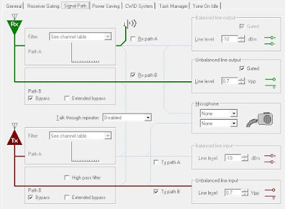
Followed by Channel Profile > Signal Path
Line Level values are selected to give as close to -10dBm in & outputs as possible. In this case 0.7Vpp did the trick.
Next navigate to Signaling Profiles > TX Timers and uncheck the Hand time checkbox.
TB8100 Auxiliary Connector
You can connect your modem to the following pins on the 25 pin D-Range connector.
PIN Name Type MMDVM Position
3 RX audio output Output RX
5 TX audio input Input TX
8 RSSI Output RSSI
9 RX Gate Output SQL
10 TX Key Input PTT
25 Ground Ground Ground
MMDVM.ini file
Lines that need to be edited are highlighted in Yellow – Critical settings are in BOLD
[General]
Callsign=ZS0ABC // Repeater Identifier
Timeout=300 // TX Time out Timer
Duplex=1 // 1 for Duplex – 0 for Simplex
# ModeHang=10
RFModeHang=10
NetModeHang=3
Display=None
Daemon=0
[Info]
RXFrequency=430625000 // RX Frequency of repeater
TXFrequency=438225000 // TX Frequency of repeater
Power=5 // TX Output power
Latitude=-29.550000
Longitude=30.052277
Height=156
Location=Durban
Description=Multi-Mode Repeater
URL=www.dmr-za.net
[Log]
# Logging levels, 0=No logging
DisplayLevel=1
FileLevel=0
FilePath=.
FileRoot=MMDVM
[CW Id]
Enable=1
Time=15
[Modem]
Port=/dev/ttyACM0
# Port=\\.\COM3
TXInvert=1
RXInvert=1
PTTInvert=0
TXDelay=60 //60 Gave best results but alter to your own needs
DMRDelay=45 // 30 works well for TM8115 & TB8100 40 for TB7100
RXLevel=50
TXLevel=90 // 90 worked for me but alter to your own needs
# D-StarTXLevel=50
DMRTXLevel=90 // Set same as TX Level
# YSFTXLevel=50
OscOffset=0
RSSIMultiplier=1
RSSIOffset=0
Debug=0
[D-Star]
Enable=0
Module=C
SelfOnly=0
[DMR]
Enable=1
Beacons=1
Id=6555XX //Your ID Here
ColorCode=1
SelfOnly=0
# Prefixes=234,235
LookupFile=DMRIds.dat
CallHang=3
TXHang=4
#Blacklist=
#DstIdBlackListSlot1RF=
#DstIdBlackListSlot2RF=
#DstIdWhiteListSlot1RF=
#DstIdWhiteListSlot2RF=
#DstIdBlackListSlot1NET=
#DstIdBlackListSlot2NET=
#DstIdWhiteListSlot1NET=
#DstIdWhiteListSlot2NET=
[System Fusion]
Enable=0
[D-Star Network]
Enable=0
GatewayAddress=127.0.0.1
GatewayPort=20010
LocalPort=20011
Debug=0
[DMR Network]
Enable=1
Address=154.66.196.131
Port=62031
# Local=3350
Password=Password Here
RSSI=0
Slot1=1
Slot2=1
Debug=0
[System Fusion Network]
Enable=0
LocalAddress=127.0.0.1
LocalPort=3200
GwyAddress=127.0.0.1
GwyPort=4200
Debug=0
[TFT Serial]
Port=/dev/ttyAMA0
Brightness=50
[HD44780]
Rows=2
Columns=16
# For basic HD44780 displays (4-bit connection)
# rs, strb, d0, d1, d2, d3
Pins=11,10,0,1,2,3
# Device address for I2C
I2CAddress=0x20
# PWM backlight
PWM=0
PWMPin=21
PWMBright=100
PWMDim=16
DisplayClock=1
UTC=0
[Nextion]
Port=/dev/ttyAMA0
Brightness=50


