Tuesday, May 13, 2025

DX Code of Conduct for the Radio Amateur - Randy Johnson, W6SJ

Image:  Click on image for larger view.

  "As a reference for myself, and for all those engaged in amateur radio, here is a copy of the DX code of conduct. You are encouraged to copy it wherever you like. To make things clearer, I numbered each rule of conduct and highlighted the most important parts." - Randy Johnson W6SJ

  1. I will listen, and listen, and then listen again before calling.
  2. I will only call, if I can copy the DX station properly.
  3. I will not trust the DX cluster and will be sure of the DX station’s call sign before calling.
  4. I will not interfere with the DX station nor anyone calling and will never tune up on the DX frequency or in the QSX slot.
  5. I will wait for the DX station to end a contact before I call.
  6. I will always send my full call sign.
  7. I will call and then listen for a reasonable interval. I will not call continuously.
  8. I will not transmit when the DX operator calls another call sign, not mine.
  9. I will not transmit when the DX operator queries a call sign not like mine.
  10. I will not transmit when the DX station requests geographic areas other than mine.
  11. When the DX operator calls me, I will not repeat my call sign unless I think he has copied it incorrectly.
  12. I will be thankful if and when I do make a contact.
  13. I will respect my fellow hams and conduct myself so as to earn their respect.

A "DX Code of Conduct Certificate" isn't a standard, officially recognized document. It's not a formal certification like a license or a degree. However, it refers to a set of guidelines for good DXing practices in amateur radio, promoting ethical and respectful behavior while operating on the air. 

Elaboration:
DXing, or "distance communication," is a popular activity within amateur radio, where operators strive to contact stations from distant locations. A "DX Code of Conduct" outlines principles for behaving respectfully and ethically while engaged in DXing.
Key aspects of a DX Code of Conduct (as reflected in the search results):

Respectful listening:
Operators are encouraged to listen carefully before calling, ensuring they can copy the DX station properly.

Avoiding interference:
It's important to avoid interfering with DX stations or other operators attempting to contact them.

Proper communication:
Operators should use their full call sign, wait for the DX station to end a contact before calling, and avoid continuous calling. 

Respect for other DXers:
It's crucial to conduct oneself in a manner that earns respect from other radio amateurs. 

Importance of ethical behavior:
Bad behavior on the operating bands can negatively impact the image of amateur radio.

In essence, a "DX Code of Conduct Certificate" is a non-official acknowledgement of a DX operator's commitment to following these principles of ethical and respectful operating practices. It's not a piece of paper, but rather a commitment to good conduct on the airwaves

Aircraft Scatter possible via the ISS during SSTV Experiment 73 Series 27 on 5 May 2025 17h03 - 17h13 SAST?


Image:  SSTV image that was downloaded by ZS1Q on the 5 May 2025 during the "strange" phenomena.

During a fly-past of the ISS on the 5 May 2025 two SSTV Images were broadcast over South Africa as part of the SSTV Experiment 73 Series 27.  A "strange" phenomena was observed by Francois ZS1Q in  George who participated in the experiment.  During the pass timeline 17h03 - 17h13 Francois observed  a strange "event". During the predicted pass moving from SW to  SE  instead of following the ISS track as predicted he received a better signal tracking the ISS from SE to SW.  He was using a portable 3 element Yagi antenna at the time.  Now one can argue that the Yagi received the signal "backwards" which I doubt because the front to back ratio of the antenna is excellent. When he told me about what he experienced I was curious to know what caused this "phenomena".  Maybe two reasons:  1.  A reflected signal from a building. 2.  Airplane scatter - Airplane scattering (or most often reflection) refers to the reflection of a radio signal by the metal structure of a passing aircraft. It is observed on radio waves from high frequency to VHF through to microwaves and, besides back-scattering, yields momentary propagation up to 800 kilometers even in mountainous terrain. 

Now we have large mountains to the North West of George and also a provincial airport to the South of  the town.  I decided to look at flights taking of and landing at the time of the ISS pass.  Low and behold FlightRadar24 indicated that  ChemAir Flight 5Z451 departed from George to Johannesburg. The flight was sceduled to depart at 16h55 SAST, actual departure was 17h05 SAST and arrival in Johannesburg was at 18h50.  The 17h05 actual departure of the aircraft coincided with the ISS broadcasting SSTV images in  the George tracking area.  What is interesting is that the ChemAir aircraft was flying in a northerly direction while the ISS moved towards a north easterly direction and the QTH of Francois ZS1Q was in between the ChemAir aircraft and the ISS.  This scenario makes it possible that a reflected signal from the ISS was bounced of the ChemAir aircraft and back to the station of ZS1Q.  Was this indeed the case?  Very difficult to tell as there was no upfront setup to work Aircraft Scatter. (Note:  ZS1Q is currently looking to see if  he can find the RAW SSTV audio file to listen to.  Unfortunately Robot36 does not save the audio file, only the image. ) 

Image:  ISS Track

However the scatter could have played a roll in the "strange" phenomena that Francois ZS1Q experienced while downloading SSTV images from the ISS on the 5 May 2025.  Never before has he experienced  "reverse" tracking while downloading images.  We will most probably never know for sure but one thing stands out above all.  If you do not experiment and participate in events you will never experience the magic of the amateur radio bands, modes, propagation and other strange phenomena.  There is still many unknowns that need to be discovered out there and in space.  Be ready for such events and participate in events and experiments.

More on aircraft scatter: 

Radio amateur usage Compared to a single trail of meteor scatter, the time of opening caused by a single airplane is longer – it can be from 30 seconds up to a few minutes. Slight asymmetry can sometimes be encountered both in terms of exact timing and the gain of the path. Range and possible contact lengths are affected by the size of the plane, flight level and the approximate crossing time of the central part of the straight line between the two communicating stations. Both the onset and decay of the channel is rapid, so to improve success rate, a short contact procedure is used. Contact opportunities can be predicted based on the precise flight paths of surrounding planes. There exists software for prediction using local (Mode S and ADS-B) or online sources. Microwave access using high gain antennas needs to consider precise aiming that takes into account elevation angles as well.

Links to Aircraft Scatter Web-Pages:


W3SZ Aircraft Scatter

7 October 2024 – Aircraft Scatter, the Hitch-Hikers Guide by Ian White, GM3SEK

SM6FHZ's aircraft scatter page:  He has an aircraft scatter path-loss Excel Spreadsheet.

SM0DFP has a page describing his use of ADS-B signals to assist with airplane scatter contacts

A PowerPoint talk by DF9IC on airplane scatter

Images:  Click on images for larger view.


Sources:  Flightradar23, Orbitron, ISS and ARISS

Monday, May 5, 2025

12 v High Current DC Power Supply Project for your Amateur Radio Equipment


A R65.00 DC Power Supply Project for your Amateur Radio Equipment.  Can this really be true?   Read on and find out.

A year or so ago I ran into three old Dell PowerEdge Servers at an auction for R50 each.  Nobody wanted them and I took them home.  All three were in a working condition but were fairly old technology.  I stored them in my container for a "rainy day".  Well the rainy day arrived in April 2025 when I ran into a short article how to convert a server power supply into a low noise 12v DC Power Supply.  Server power supplies are noisy and when the fans run at full speed it sounds like a turbo jet. Very very noisy indeed!

I intended to scrap two of the servers and keeping the smaller one for another "rainy day".  After stripping of the servers I was left with many usable parts.  I looked at the 4 x power supplies and realized that the one server's supplies does not have fans embedded in the power supply casing.  However these two units were fed with air that circulated inside the server.  These two looked like good candidates to modify into a low noise 12v DC Power Supply for Amateur Radio Equipment.

Here are some images of what the Server Power Supply looked like before any modifications.  (Click on images for larger view.)


Herewith the specifications of the Dell Model D670P-S0:

Dell D670P-S0 SERVER POWER SUPPLY

The Dell D670P-S0 is a 670W power supply unit (PSU) with a 100-240V input, designed for Dell PowerEdge 1950 servers, and features a 54.4A +12V output and a 5.25A +3.3V standby. 

Here's a breakdown of the Dell D670P-S0 power supply specifications: 

  • Model: D670P-S0

  • Power Output: 670W

  • Input Voltage: 100-240V

  • Input Current: 10A / 200-240v 4.8a

  • Frequency: 47-63Hz

  • Output:

    • +12V: 54.4A

    • +3.3V Standby: 5.25A

  • Designed for: Dell PowerEdge 1950

  • Other Notes:

    • Hot-plug capable

    • May be used for 12V bench supply with some modification

    • Requires jumper connections to enable 12V output

    • Jumper pin A1 to A3 (ground)

    • Jumper from B6 (12V power enable) to B3 (ground)

WARNING:  Please note that all server power supplies does not have the same jumper pin and power outputs.  Ensure that you have all the information of the server power supply you want to modify.  If not sure then do not go ahead with the modifications.  Take care when working with any power supply as high voltages are present that are lethal and will kill you if you make mistakes or by accident.  You have been warned!!

TAKE NOTE:  For use as a power supply for Amateur Radio it may be best that the case be left connected to -12v.  This may help to reduce RF noise from the switching power supply but experimentation will have to be done as to the best way to eliminate the RF.  Interference will not be an issue on VHF radios but on HF radios the lower bands might be affected and is so RF filtering will be required.

Before I continue to explain how I went about to modify the Dell D670P-S0 Server Power Supply it is necessary to make mention of the fact that this project is not my idea or invention.  I visited several Internet sites to gather information to undertake this project.  There are an abundance of information on the Internet in this regard.

If you plug in the 220v AC plug the unmodified server power supply will not produce any 12 v output. We need to install jumper connections to enable 12 v DC output.  Lets look at the pin header that will host the jumper connections.

Image:  Pin Header (Click on image for large view.)

STEP 1:  Enable other Futures

For the Dell D670P-S0 power supply we need to jump pin A1 (plugged in) to A3 (ground)  This jumper does not seem to alter power supply state in any way, other than to enable other features to work. There is no reason not to make this connection permanent if the supply is no longer being used in a Dell chassis.

STEP 2:  Enable Main Power Output

Jumper from B6 (12V power enable) to B3 (ground). This should enable the main power outputs.  We will be adding an OFF / ON Toggle Switch between these two pins.


STEP 3:  Pin Diagram - Other Features

I use female DuPont cable sets for connecting the pins. They fit tightly and prevent any short circuiting to other pins. I added the off/on switch at a later stage as I wanted to see if the server power supply would startup correctly.

Now that we have all the pins connected it is time to add 220v AC to the input and measure the output voltage at the PB connectors.  After switching on the 220v AC Input and a few seconds later the 12V DC Output came to life.

Take note that this power supply has no fan, so do not let it run for long periods until you installed a fan.  The supply can get hot quickly and we do not want to damage the supply before all the modifications have been completed.

The next awkward modification is to modify the - Neg and + Pos connecting pins.  I tried to solder thick copper wire to the PB pins but solder would not take on these pins.  Now either the pins were very dirty or my soldering iron was on the cold side.  Instead of trying to clean the pins or stuff up the pins I decided to use electrical female spade connectors that fits nicely over the PB pins.  I soldered thick copper wire to the spade connectors and plugged the negative and positive "connectors" into the server power supply.  Joining the outputs together like I did will provide 54 Amps of current.  You can also make three output connections giving you about 18 Amps individually. 


Once this modification is complete you may solder the output wires (Black + Red) to the thick copper wire and you are ready to use the power supply. If you tied the outputs like in the image above use 4.8 mm wire @ 54 Amps .  If not tied use 2.6 mm wire @  3 x 18 Amps. 

I wanted something that looked better and that protects all the connections, furthermore the fan needed to blow all the air through the supply.  Leaving it open will not provide sufficient air flow.  I found a 3D printer cover for the server power supply.  After printing the cover on my 3D printer I was not happy with the strength, thickness and cover distance of the cover.

I decided to roll my own cover with Free-CAD and printed the cover on my 3D printer.  I added the On/Off switch between B3 and B6.  As mentioned before this server power supply has no fan to keep it cool.  No problem!  I took one of the server fans but from experience I know that when these fans run at full speed they make a heck of a noise.  To curb the noise but still have a decent amount of  airflow in the server power supply, I had to either control the the fan using a thermal switch or install a switch between B2 and B3. Open is Hi,  Closed is low.

I however choose the easy way out by adding a resistor in the positive line of the fan.  I used a 47 Ohm 5 watt resistor.  You can play around with the value of the resistor but ensure that you use a 5 watt component as this resistor gets fairly hot.  To keep this resistor as cold as possible I mounted it on top op the pin connectors where the fan can furthermore keep the resistor and the power supply unit cold.  This is an easy solution and worked like a charm.


After all the connections was made I used the hot-glue gun to "isolate" them.  Furthermore the hot-glue prohibit the wires from breaking off or become loose.   Next I installed the fan, switch and black compression glands.  It took some effort to fit everything through the open end but I managed to complete the task.  Next time I will re-design the 3D cover to make it easy to fit all the parts and components.

Once again time to test the modified server power supply.  The end result is a working 12.37v DC,  54.5 Amp power supply.  Most of the server power supplies do have different protection circuitry, however I chose to add my own Crowbar Unit to this supply for "extra" protection.  More on this project, click HERE.

Finally:  Total cost of this project amount to R65.00 (excluding the add on Crowbar Unit.)  I will test this supply further and will do a follow up article on my findings.  So far I think all the effort was worth it and I am now the proud owner of  a high current DC power supply.

Images:  (Click on images for larger view.)


Friday, May 2, 2025

Down Memory Lane: Garden Route Amateur Radio Event - Hunting Lions on the Air! (14 January 2004)


I scratched around my archives and ran into the following photos. The event took place in the George area close to the George Airport on the 14 January 2004.  Who still remembers "Hunting Lions on the Air!"  

For those not familiar with this contest,  I provide the following AI information:

"Hunting Lions on the Air" is an international amateur radio contest organized by Lions Clubs in memory of Melvin Jones, the founder of Lions Clubs International. Radio amateurs operating on behalf of Lions Clubs participate by making radio contacts, and the contest focuses on identifying and making contact with specific Lions Club stations. 

Elaboration:

Lions Club Involvement:  The contest is sponsored and organized by Lions Clubs, a global service organization, in commemoration of their founder.

Radio Amateur Participation: Radio amateurs, or "hams," participate by making radio contacts with stations operating on behalf of Lions Clubs. 

Objective: The primary objective is to locate and make radio contacts with stations operating for specific Lions Clubs. 

Contest Structure: The contest is divided into classes, with Class 2 contestants being radio amateurs operating on behalf of a Lions Club. 

Historical Significance:  The contest has a long history, with the BV2B station in Taipei being a prominent participant.

The Hunting Lions on the Air event that took place on the 14 January 2004 and was organized by the Late Alan Franzen ZS1FG ( ex ZS6BIK)  Alan lived in George for a period of time and he invited all radio amateurs in the Garden Route Area to spend the day at his QTH.  Before I continue I must mention that Alan was a dynamic radio amateur and person.  Herewith a short overview:

"Alan had been a friend of Amateur Radio for so many years and involved in so many aspects, that when the Antique Wireless Association of Southern Africa - ZSØAWA was launched it was not unusual to see him join us with all his ideas for promoting the use of valve radio’s and antique collections. He was instrumental in the forming of the “Mission Statement” and every year promoted the voting for a new President, but never wanted to be President himself. It was due to his efforts that the call sign ZS0AWA was allocated to the association. There were many different aspects to Alan’s involvement in Amateur Radio, and he will surely be missed.   Alan's key went silent in 2008."  =  AWA

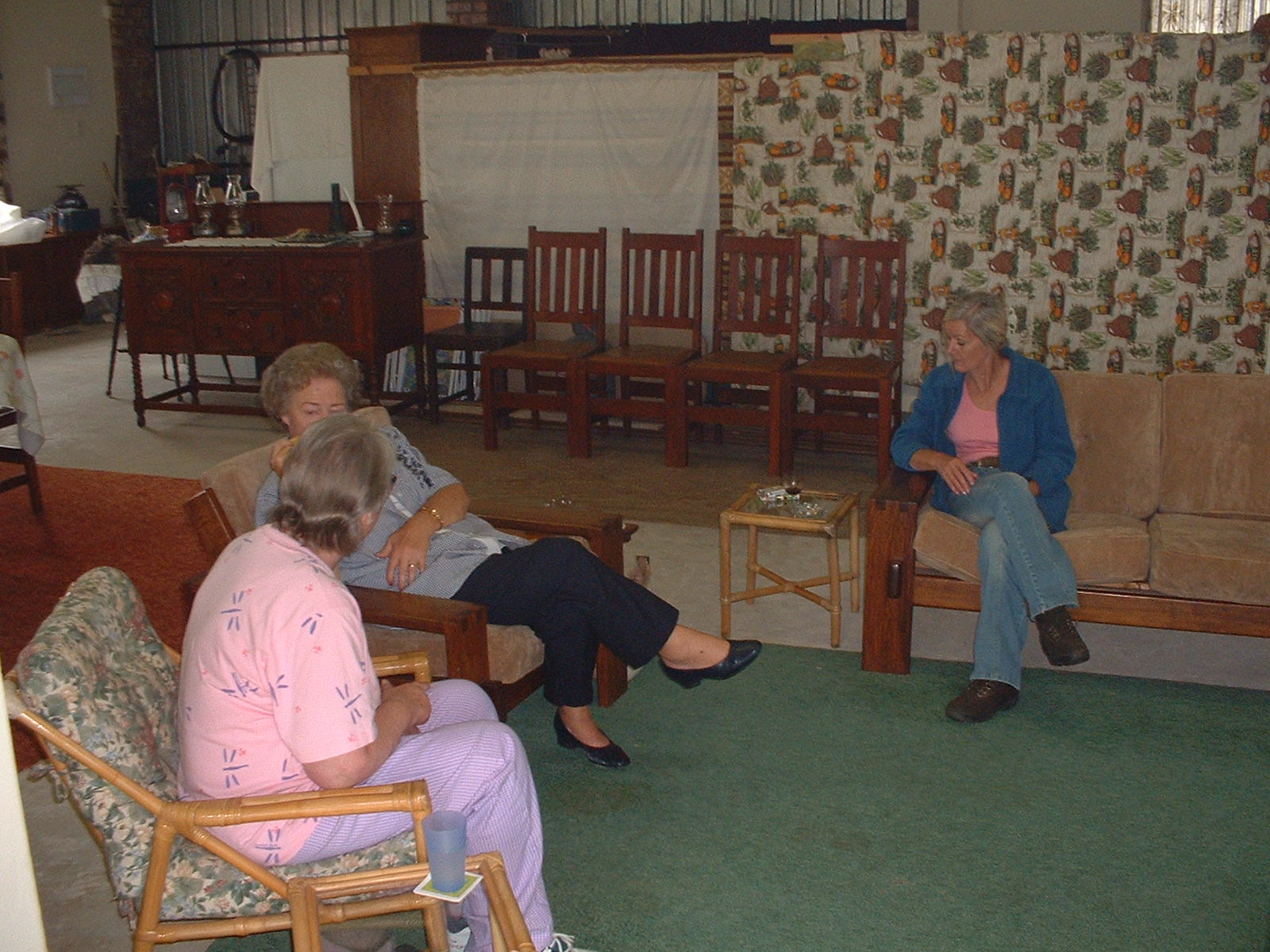
Many others in the photos are today also silent key, amongst them the well known Ruth Boatwright ZS2QK who was a "white stick" operator as she would called herself.  (Images:  Ruth is wearing dark glasses.)

Finally:  I hope these image bring back good memories, to fellow radio amateurs in the Garden Route Area and those who knew Alan Franzen ZS1FG.

Images:  (Click on images for larger view.)

Image 1 + 2:  Alan ZS1FG 


Images 3 - 5:  Casey Nootenboom ZS1AAS


Images 6 - 7: YL's

Image 8:  Braai Time!!

Tuesday, April 29, 2025

Cape Agulhas AllStar Node now active on the Southern Cape AllStarLink Network

Yet again another AllStar Node has joined the Southern Cape AllStarLink Network.  This time it is the node of Bernie ZR1ACP from Cape Agulhas.  Bernie lives in the Cape Agulhas which is located in the Overberg region, 170 kilometres (105 mi) southeast of Cape Town. It is the geographic southern tip of Africa and the beginning of the traditional dividing line between the Atlantic and Indian oceans according to the International Hydrographic Organization.  Another well known landmark is the Cape Agulhas Lighthouse.  The above 360 degree image was taken from the lighthouse.


Image above:  Where the Indian- and Atlantic Ocean meets (Click on image for larger view.)

Image above:  Cape Agulhas Lighthouse  (Constructed  in 1848 (first lit 1849))

Now lets look at the ZR1ACP AllStar Node particulars:


Herewith information and connection details:

Node Number:  62609
Node hardware = Raspberry Pi 3
Link Radio = Baofeng 888 
Frequency = 433.525 Mhz
USB Fob = CM108
AllStar Software = HamVoip / Supermon
Location:  Cape Agulhas, South Africa
 
Finally:  The ZR1ACP 62609 AllStar Node is daily connected to the 49355 ZS1I AllStar HUB, Mossel Bay. Next time you on holiday in the Agulhas area you most welcome to use the node to talk to the World.  A big thank you to Bernie ZR1ACP who undertook this project and made it a reality.  Well done Bernie!!  The ZS Link Network Group welcomes the Agulhas Node to the AllStarLink Network in South Africa!
 
Images:  (Click on images for larger view.) 


Closure of this ZS Link Network Blog - 29 April 2026

This will be the final posting on the ZS Link Network Blog. This blog will no longer be updated but will remain available for research an...