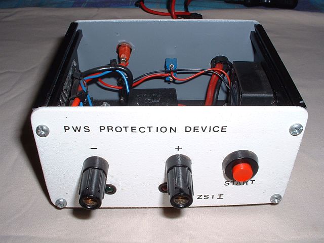
I know that there are many articles on the Internet relating to an over-voltage protection unit for your power supply. However after constructing the Heavy Duty Power Supply described by Andre ZS2ACP a while ago in QSX, I looked again at the over voltage protection circuitry. A thought came to mind that a separate PCB that hosts the over voltage protection components could come in handy especially if you have a power supply with no such protection. As this is a simple project, I will not go into all the detail to construct the protection circuitry other than providing you with the component overlay (Fig. 1) and a photo of the prototype project. I changed the PCB outlay to suite my needs and came up with a board as shown in Fig. 2. (Not to scale) Just a word of advice. Use thick and short wire on the input as well as the output side depending on the amount of amps your power supply provides.

Above: Figure 1

Above: Schematic Diagram
COMPONENTS:
1. D1 = GREEN LED
2. R1 = 1K2 RESISTOR
3. K1 = RELAY 30 AMP AUTO 12 VOLT
4. K2 = RELAY TAKAMISAWA RY5W-K
5. S1 = PUSH SWITCH
6. Q1 = BC 108 OR BC 109
7. R5 = 1K RESISTOR
8. D2 = 13V ZENER DIODE
9. R4 = 10K RESISTOR
10. R2 = 470 OHM 5 WATT RESISTOR
11. C1 = 0.01 CAPACITOR
12. C2 = 0.0001 CAPACITOR
13. C3 = 0.1 CAPACITOR
14. R3 = 470 OHM RESISTOR
15. D3 = RED LED

Above: Figure 2 (Not to scale)
Enjoy building this handy little unit. It could save you a lot of tears if your power supply decides to go “silent key”.


