I decided to build myself the PIC16F84 -Based CW Decoder as described in QST August 1999 by Francesco Morgantini, IK3OIL. The project was build in June 2008.

Although designed primarily for learning CW, new and experienced CW operators are sure to like this simple and inexpensive CW decoder!
This project arose from a three fold need. Firstly to brush up my CW receiving which is currently completely rusted. Secondly to monitor the HF Beacon Project and thirdly to monitor the VHF Beacon Project. Please note that this decoder cannot substitute the ear's and brain's interpretation capability nor other similar instruments can do that. At the most they can help in quickening the morse code learning. The decoding capabilities are essentially connected to the received signal quality, it must be clear and strong enough, so don't think you can decode a weak and vanishing signal in the QRM, if this is your goal, you should much better make use of your ears. If however the signal is good and stable enough, then this equipment can succeed in doing its job well, adapting also itself to the CW rate, provided that it is sufficiently regular. However the project could be of great assistance to the newcomer who tend to be nervous and have difficulty copying during their initial CW QSO's. The alphanumeric readout helps you cope with band conditions and variable sending speeds, too. With a decent incoming signal level, this decoder performs well, automatically adapting itself to the incoming CW at speeds between 5 and 30 WPM.
Specifications:
The device is equipped with a 2x16 LCD display , the text shifts from left to the right starting from the end of the second row. An inter-words automatic spacing function is provided, based on a regular timing of the pauses in the sent code. This function may be inhibited grounding the J pin if the device is used for training purposes or while receiving an improperly sent code. The audio input must be at least 100 mV pp, a clipper is provided to cut large signals. The band width is about 100 Hz and the center frequency may be adjusted between 700 and 1000 Hz by a trimmer. A service push button (P1) displays the keying rate in chars/min, this measure is refreshed every N received characters (N is a settable software parameter). An input is provided for a straight Key, and both inputs (audio and key) activate the code display and the audio monitor function, a LED is operative while receiving code and shows the correct lock to the audio input, these two monitoring functions are very helpful to adjust the receiver tune because of the narrow bandwidth of the decoder. The BF monitor can drive a 32 Ohm earphone with the two sides series connected. The Vcc can be supplied by a 9V transistor battery and requires about 15 mA. An external supply (min 9V) is however recommended for long time use. When powered on, the microprocessor is set for an intermediate keying rate, some characters may be therefore required to reach the lock with the received signal if it is very slow or very fast.
The software developed makes use of the assembler PIC16 language and run on a PIC16F84 microprocessor. It takes a measurement of the received signal ON and OFF time, obtains some statistical mean values, and calculates three parameters which are then used for decoding. An interword automatic spacing function is provided, based on a regular timing of the pauses in the code received. If the decoder is used for training purposes, or while receiving improperly sent CW, the interword spacing can be turned off. With the interword spacing turned off, received characters follow one another in a single continuous alphanumeric string. The decoder's initial setting is approximately 15 WPM and is refreshed every 15 dits or dahs received. The character set includes all letters, numbers, 0 through 9, the period, comma, hyphen, double dash and question mark. Unrecognized characters are displayed as an asterisk. (*) The prosign SK is displayed as an (#).
Circuit Description:

The schematic appears very simple, actually almost all of the functions are performed by the microprocessor software, while an NE567 tone decoder takes charge of processing the audio input signal. This IC contains a PLL circuit whose lock frequency may be adjusted between 700 and 1000 Hz by the RV2 trimmer. With the listed component values a bandwidth of about 100Hz is obtained. The PLL measured lock delay is about 10 mS. A clipper is provided to limit the input signal amplitude, it is obtained by 2 germanium diodes. Pin 8 of the PLL drives on gate of the CMOS trigger NAND 4093 whose output is connected both to the microprocessor gate and to a second CMOS gate working as an audio generator. The remaining two 4093 gates are used to implement a buffer capable of driving a medium impedance load (64 Ohm). A 78L05 regulator supplies both the decoder module and the LCD display with power. RV1 trimmer is used to adjust the display brightness. The only other required tuning is the RV2 trimmer to obtain the best frequency lock using an input CW signal strong and clear from your receiver.


TOP: LCD showing DE ZS1I BEACON K decoding

TOP: The Morse Code Decoder being tested on the test bench.
I finished the Morse Code Decoder Project. Here are some photos of the finished decoder. I tested it with the local 80m beacon and it seems to work fine. However the proof is in the pudding and I will test the decoder soon on the 20 meter band. I will also add my morse key to it and test my ability to send morse at a reasonable speeds. I will give a full report of the final tests soon.
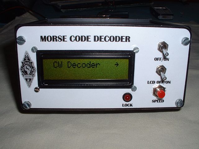
Above: Completed Morse Code Decorder

Above: Inside view of the decoder. I added a 5V power supply(back PCB) backup for the LCD backlight as with the on board power supply the LCD tends to "flicker" while the CW was decoded. With the backup power supply this problem was solved.

Above: Rear view of the Morse Code Decoder
Morse Code Decoder Review:
This is my personal observations relating to the Morse Code Decoder. As already mentioned supra this decoder was developed by IK3OIL primary for learning Morse Code. Please note that this decoder cannot substitute the ear's and brain's interpretation capability nor other similar instruments can do that. At the most they can help in quickening the morse code learning. The decoding capabilities are essentially connected to the received signal quality, it must be clear and strong enough, so don't think you can decode a weak and vanishing signal in the QRM, if this is your goal, you should much better make use of your ears. If however the signal is good and stable enough, then this equipment can succeed in doing its job well, adapting also itself to the CW rate, provided that it is sufficiently regular. However the project could be of great assistance to the newcomer who tend to be nervous and have difficulty copying during their initial CW QSO's. The alphanumeric readout helps you cope with band conditions and variable sending speeds, too. With a decent incoming signal level, this decoder performs well, automatically adapting itself to the incoming CW at speeds between 5 and 30 WPM.
This was a very satisfying project to build and after completion that feeling only experienced by home-brewers rose within my system. Truly the symptoms of the "knack" was treated with this project. Enough let's get to the bottom line of this decoder. Although the decoder was used once or twice to monitor the 7Mhz Beacon in George and the 3.5Mhz Beacon in Mossel Bay, I could really not judge the Morse Code Decoders performance.
The first opportunity to really test the decoder arose during the SARL CW Contest that took place on 31 August 2008. I used the following equipment to monitor signals. Yaesu FT817 connected to the Morse Code Decoder. I used a Rally Trap Antenna for 40 and 80 Meters. It was possible to decode several stations , but not without some letters going astray. It was however possible to receive 85% of the CW send during the contest although band conditions was rather poor.
Finally: This is really a super little project that assisted me to brush up my CW again. Many thanks to Francesco Morgantini IK3OIL for making this project available to interested radio amateurs!


