Disclaimer:
The project discussed under this topic uses lethal voltages and should
not be attempted by those who are not properly experienced. Proper
safety precautions must be adhere to at all times. I will not be held
responsible for your actions. Use at own risk.
This project was published in QSX the PEARS monthly newsletter as a high
power, Power Supply. The original article appeared on Packet under the
call of ZR6CPB while Andre Botes ZS2ACP compiled the QSX article. I have
re-drawn the circuit and made a few alterations to the original PCB as
suggested by ZS2ACP to suite my needs. Alternatively I have changed the
components and PCB to use the project as:
1. Variable Power Supply 13.8v 10 Amps. ( Can easily be changed to 13.8 and 24v 30 amp by altering the PCB.
2. Lead Acid Battery Charger to charge a 12V, 100Ah battery.
Image: Photo of PCB + Components.
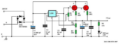
Power Supply Diagram (Click on image for larger view.)
Image: Component outlay
Image: PCB Outlay (Can be extended to accommodate 24v 30 Amps)
Parts List:
L200 IC Regulator
Bridge Rectifier 15 Amp
C1 = 10 000uF 40v Electrolytic Capacitor
C2 = 0.1uF 50v Ceramic Capacitor
C3 = 0.1uF 50v Ceramic Capacitor
C4 = 1000uF 50v Electrolytic Capacitor
C5 = 0.1uF 50v Ceramic Capacitor
R1 = 1K Variable Potentiometer 0.4 Watt
R2 = 0R2 10 Watt Resistor
R3 = 0R2 10 Watt Resistor
R4 = 10K Variable Potentiometer 0.4 Watt
R5 = 890 Ohm 5 Watt Resistor
R6 = 470 Ohm 1 Watt Resistor
D1 = Red Led
TR1 = 2N3055 NPN Transistor
TR2 = 2N3055 NPN Transistor
0 - 36 Volt 10 Ampere Transformer
Heatsink for 2N3055 Transistors
Heatsink for L200 IC Regulator
4mm Red Binding Post 20 Amp
4mm Black Binding Post 20 Amp
Amp and Volt meters to choice
2 x Transistor Isolation kits
LED holder and clip
Fuse Holder
Mains Connector
Nuts and Bolts
Metal Cabinet
ON/OFF Switch
Construction details:
This circuit and project is simple and to the point. Builders adhering to ordinary power supply practices should not experience any problem. The PCB accommodate two emitter resistors that can handle 10 amps max. The L200 and pass transistors must be mounted on substantial heat-sinks. The transformer, bridge rectifier and smoothing capacitor may be chosen for the voltage/current required.
Appropriate meters can be added for Voltage and Ampere measurement.
Transistors TR1 to TR2 (2N3055) must be fitted with TO3 thermal washers and spigots. Use heat sink paste to give good thermal contact. Check that the collectors, emitters and bases of TR1 to TR2 are a very high resistance to ground (i.e., not short circuited).
Before switching on the power supply, I would suggest that you check your work thoroughly. Make sure there is not short circuits, bridges and wrong component installations. It there is, fix them and you should pass the "smoke test". If you don't fix them then the familiar electronic smell, first the heat and then a stinky smell and up comes the smoke. Don't worry this has happened to many a good homebrewer.
Once you are convinced that everything is OK, you can throw the switch, wait a few seconds, search for smoke and if none, then you have built yourself a working variable voltage and current power supply for the test bench. Enjoy!!
Nico ZS4N build this power supply and talks greatly of it. He use this power supply on a daily basis and has not experienced any problems. Here are some photos of his project. He used an old UPS box as a cabinet and indicated that he must still do the final cosmetic touches to the power supply.
Image: Power Supply constructed by Nico ZS4N. (Click on images for larger view.)


