Image: VK2ZOI (Click on image for larger view.)
This is the 2m / 70cm Half-Wave antenna using white 25mm electrical conduit - to build a dual bander antenna.
The basic half wave version of the Flower Pot antenna can be readily modified to dual band the antenna for operation on a band that is the (approximate) third harmonic of the fundamental resonance.
Operation on the third harmonic is achieved by using a sleeve technique so as to form quarter wave phasing sections (at the higher frequency) to end feed two half waves in phase at the third harmonic.
This arrangement provides useful gain (3dBd) on the higher band. The sleeve technique maintains the impedance matching for both bands and (probably fortunately) there is sufficient longitudinal impedance in the choke coil to provide the required isolation at the third harmonic.
I decided to build this antenna as part of the New Series - Building Low Budget Antennas. Here is my version of the above antenna:
General Specifications:
Resonant Frequency: 145.250 Mhz
Frequency Span: 144.200 - 145.800 Mhz
Modes: FM ( Local repeaters and simplex)
Polarity: Vertical (Note: Repeaters use vertical polarization.)
Antenna Impedance: 50 Ohm or very close to 50 Ohm
Gain: Some gain but could not find any scientific proof
I found a very useful Flower Pot Antenna Calculator if you want to change the measurements to suite your needs. This calculator is used to determine the length of each element of the flower pot antenna. That includes the upper radiator, lower radiator, also the length of the cable that will be wound on the PVC pipe.
The calculator is available HERE
Enough said let's start building the Half-Wave Flower Pot Antenna.
Materials I used:
Cable Ties
Solder
Solder Paste
5 -10 m Coax Cable (RG58CU Mil Spec) 50 ohm with 2 x Connectors (Feeding line to radio)
Self Amalgamating Electrical Tape
PVC Cement ("Glue") (Permanent gluing of the PVC caps.)
Tools:
Metal Punch
Drill
Drill Bits 6 mm + 3mm
Hack Saw or PVC Pipe Cutter
Hot Glue Gun
Soldering Iron
Sharp Utility Knife
Screw Driver (Small flat)
Test Equipment:
VHF SWR Meter
Antenna Analyzer (If you have one but not compulsory)
VHF/UHF Radio
Coax Patch Leads
Mast (Non conductive)
Power Supply or Battery for Radio
Building the Antenna:
I am not going to go into detail how I constructed my version of the antenna as there is more than enough info on the Internet how to construct the antenna. Herewith a few links:
Flower Pot Antenna - How it works:
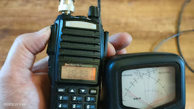
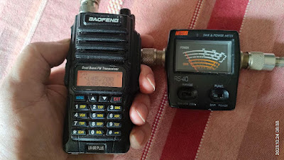
This antennas has been given several names like:I ran a quick test on the antenna with my HT just to see what the SWR was like. Well the images speak for themself. SWR was low over a very broad spectrum (144.300 - 145.800 Mhz). In my case this antenna works better than one of my Diamond X50 antennas. But in all fairness I think the Diamond antenna might have a problem. With the Flower Pot antenna about 1 m above the roof I can work the 145.750 Mhz Aasvoelkop Repeater with 2 watts which I cannot do with the Diamond X50 which is about 3m above the tiled roof. I could also trigger all the local repeaters in the George / Mossel Bay area with two watt output. I will do some more tests once I invest in a VNA Antenna Analyzer. More on this in a future posting.
Conclusion:
This antenna will be great for HOTA, SOTA, POTA and even Emergency Communications. It is lightweight and easy to setup/install. To the new radio amateurs this antenna is an ideal first time antenna project. Give it a try and forward your build images to me for posting on this Blog.
Images: Click on images for larger view.


