UPDATED: 2 May 2023 16h48 SAST
The cubical quad antenna is without doubt one of the best DX antennas currently available and is a proven performer! The circular quad described by Christi ZS4CGR HERE is in my opinion better than a square quad antenna. The circular quad has a higher gain than any other antenna of similar dimensions and is also cheap to construct but not as cheap as this square cubical quad antenna.
Now back to the square cubical quad antenna that I will be constructing. One of the greatest advantages of the quad is that it exhibits a lower angle of radiation than a Yagi at heights of less than one wavelength. This makes it a great antenna for working long distances as more of the power is radiated at low angles even if you can't get them mounted as high as you would like.
One of the reasons for the effectiveness of the quad antenna is the fact that it not only exhibits more forward gain and a very good front to back ratio but also it has a larger physical capture area than a Yagi of the same boom length. Each element is a full wavelength in size compared to a Yagi which has elements of only one half wavelength making the quad a far more effective antenna for both TX and RX.
As with any antenna the true performance is only achieved when all elements are resonant at their correct frequencies and also when the feed point is matched correctly and the antenna is installed as high as possible from the ground or the roof.
The quad antenna makes an excellent base or portable antenna. Another plus is that its directivity also makes it very well suited to fox- or transmitter hunting. (ARDF)
Lets look at a few nice to know aspects of this antenna:
- Gain vs Spacing - The gain of an antenna with parasitic elements varies with the
spacing and tuning of the elements, and thus for any given spacing
there is a tuning condition that will give maximum gain relating to
this spacing. The maximum front to back ratio seldom, if ever occurs
at the same condition that gives maximum forward gain. The impedance
of the driven element also varies with the tuning and spacing, and
thus the antenna system must be tuned to its final condition before
the match between the coax and the antenna can be completed. However,
the tuning and matching may interlock to some extent, and it is
usually necessary to run through the adjustments several times to
insure that the best possible tuning has been obtained.
- The feed point of a full wave length cubical quad has a characteristic impedance of approximately 115 ohm. The shape of the "loop" determines the impedance and gain.
- In this build I will be using 75 ohm RG59 U coaxial cable for the impedance matching transformer. This match will bring the impedance very close to 50 ohms. I attached 10 meters of RG58 CU Mil Spec coax to the 75 ohm coax as feeder line.
- This Quad can either be used in the vertical- or horizontal polarization configuration. The polarization of the Cubical Quad loop depends on the location of the feed-point. If the loop is fed in the middle at the bottom or top, then it produces horizontal polarization, whereas if it is fed in the middle of one of the sides (or a side apex in the case of diamond orientation), then the radiation polarization is vertical.
- One of the biggest advantages to using the quad loop that it is impervious to rain/sleet/snow/sand static noise. Have you ever had rain static pound your receiver when a rain storm was rolling in? Things such as sand and rain carry an electrical charge that cause a lot of noise on verticals and Yagi beams. Surprisingly, the closed loop of the quad does not respond (pick up) to this type of noise.
- Some claim a quad element has less noise than a dipole. There is a very limited amount of truth behind the "quads/loops are quiet" myth. The blunt ends of a quad loop are at the high impedance voltage points, rather than the sharp projected tips of a Yagi. This can reduce effects of precipitation static.
- There is a secondary less commonly thought of reason for less local noise pickup. Many Yagi antennas and dipole antennas have poor baluns or no baluns at all. This leaves the yagi or dipole susceptible to common mode RF pickup on the feed line. This is the electrical equivalent of having a very poor shield on the feed line. The quad, even without a balun, is very much less sensitive to feed line common mode. This is because the quad is not a low impedance source for common mode currents and often cannot drive the shield as effectively as a dipole with common mode currents.
- There is one other condition where a 2-element quad might have a slight advantage over Yagi. That would be when strong noises or unwanted signals arrive from the rear, and the quad has been adjusted for maximum F/B ratio. This advantage, like the gain differences, vanish as more elements are added.
- Finally: Compact and lightweight, Commonly available hardware materials, Portable, break-down construction and stores nearly flat, Easily switched between vertical and horizontally polarization and covers the entire 2m band in SA with low SWR (<1.2:1), relative easy to construct (No special tools needed.) and finally easy to tune with a VHF SWR meter.
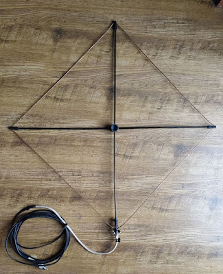
We now have enough evidence to build a small, lightweight, collapsible, portable Two Element Quad Antenna for the 2m Band. (I chose 144.250 Mhz for the center frequency)
You will need:
MATERIAL:
1 x 6m length of 20mm white electrical PVC pipe
2 x 20mm grey PVC couplers (available from your local Co-Op)
1 x 20mm grey PVC T-coupler (available from your local Co-Op)
1 x 3m x 6mm glass fiber rods (6mm wooden dowel can also be used but they are not as strong)
1 x 35cm x 10mm outside diameter with 5 mm inside diameter hole, rubber petrol pipe
1 x 460cm x 2.5mm earth copper wire (No PVC insulation)
8 x 12mm stainless steel self tapping screws
1 x 1820mm x 16mm diameter wooden dowel
1 x 5 mm Electrical Terminal Strip
1 x 45 cm good 75 ohm RG59U coax cable. I used RG6U coax
ODDS AND SODS:
Cable Ties
Hot Glue Sticks
Insulation Tape
Solder
Solder Paste
Coax Cable (RG58CU Mil Spec) 50 ohm
PL259 Connector
Masking or Painters Tape
SO238 Barrel Connector
Self Amalgamating Electrical Tape
2 x Stainless Steel U Clamps
PVC Cement ("Glue")
TOOLS:
Metal Punch
Drill
Drill Bits 6mm + 3mm
Hack Saw or PVC Pipe Cutter
Hot Glue Gun
Soldering Iron
Screw Driver (Small flat)
TEST EQUIPMENT:
VHF SWR Meter
Antenna Analyzer (If you have one but not compulsory)
VHF Radio
Coax Patch Leads
Mast (Non conductive)
Coax feed line cable 5 - 10m RG58CU 50 ohm
Power Supply for Radio
CONSTRUCTING THE ANTENNA:
Now before we can start with the construction we need to look at how to drill the spreader holes "very" accurately. Now I am sure that there are many ways to do this and you choose which ever way suites you the best. I used the following guide and template to get the holes align as accurately as possible:
- Self invented template which you can draw on a piece of paper
- Homebrew Drill Jig Guide described HERE and HERE
Self invented template:
Image: The self invented template (Click on image for larger view.)
Click on images for larger view.
The images are self explanatory and I do not deem it necessary to go into further detail as how to draw the self invented template.
Homebrew Drill Jig Guide:
You really do not need to construct this guide to build this antenna. If you have a drill press with a drill vice you can measure out and mark where to drill the holes and then proceed in drilling the holes. But for those who would like a steady and true guide, then build this jig. It served me well and I did not waste any couplers due to skew drilled holes. Just a word on the marking of the holes. I used a permanent marker. I place the coupler on the circle in the self invented template. You can then mark the coupler on the sides with a dot or line moving up the coupler. That's it you should now have 4 markings A, A, B and B. More on the final markings follow.
Links to this Drill Jig Guide appear above.
Final Markings of the 2 Spreader Couplers:
The following four photos show where I drilled the holes on the two couplers . (Click on images for larger view.)
Just a word on the marking of the holes. I used a permanent marker. I place the coupler on the circle on the self invented template. You can then mark the coupler on the sides with a dot and then to a line moving up the coupler. That's it you should now have 4 markings. Mark them A, A, B and B. Now measure 8mm from the side of the coupler up along the line and make a cross line. This is the one A and where you will drill your hole. 8mm from the side. Now do the same on the bottom line. This is the other A and where you will drill your hole also 8mm from the side. Place the coupler with the flat spot bottom down in the guide if you use one. Ensure it lies flat in the guide. Now drill the holes. Holes for spreader one is now done.
Now turn your coupler to the dot/line that is not drilled. Measure 10mm from the side of the coupler up along the line and make a
cross line. This is the one B and where you will drill your hole. 10mm
from the side. Now do the same on the bottom line. This is the other B
and where you will drill your hole also 10mm from the side. Holes for
spreader two is now done. Hint: Use a small 3mm drill bit to drill the first hole and then use the 6mm drill bit. Mark and drill the other coupler exactly the same way.
You should now have two couplers drilled.
Constructing the Reflector:
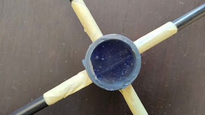
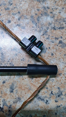
Now lets cut the 2 fiber glass 6mm spreaders for the reflector. Each spreader must be 74.5 cm long. You can now push the first spreader through the drilled holes for spreader A. To center the spreader measure 35.5 cm from the side of the coupler. The other side should also be 35.5 cm. Do exactly the same with spreader B. Once both A and B is aligned use masking tape to tape around the rod on all four sides of the coupler. (See image) This will prevent the spreaders from moving around and out of line. Now close the outside point of the spreader with masking tape as we will now add hot glue inside the coupler to fix the spreaders. You can now add hot glue from the other side. Be very careful not to mess hot glue on the section that will go into the boom. I found that the glue gun must be very hot. I drop some glue wait for it to dry and then add some more. This ensure a solid plug without bubbles. I fill the spreader up with hot glue about 2mm above the inside spreader leaving 15 mm to plug the boom into. Wait for the glue to dry and then remove the masking tape from the coupler and the spreaders. You will now have a very solid X with a coupler to fit to the boom but first we need to add the rubber pipes and copper wire. Lets cut the rubber petrol pipe. We need 8 x 30mm pieces. Once cut we need to drill a hole 8 mm from the one side of the 30mm piece. I used a 2.5mm drill bit. Once drilled take 4 of the pipes and add them to the ends of the reflector. 10 mm pushed into the fiber rods. (See image) Important: Ensure that the distance between spreader A and B at the top (where the copper wire threads through the rubber pipe) is exactly 54.41 cm on all four sides. You can push or pull the rubber pipes in or out to achieve the exact length. Once done we can now add the copper wire. Cut a piece of copper wire with a length of 250 cm. Once cut put one end into the work vice and the other end in a battery hand drill. Now wind the wire up by using the drill. Do this slowly. You will see that the wire winds up nicely and become far more firmer than before. Once you happy you can release the wire from the drill and vice. You will find that the length of wire is now much shorter than 250 cm but still long enough for the reflector. Take the wire and your permanent marker and measure the wire into 54,41 cm lengths marking each length. These markings will be your guide to where the wire must be bend at 90 degrees to fit into the drilled rubber pipe holes. Once marked you can thread the wire through the holes of the spreaders and bend them 90 degrees at the pipe holes where your markers are. You should now have a square loop. Now we need to make final measurements. (54.41 cm each side) Take one electrical terminal strip block and place it flat on the work bench. Put the reflector parallel to the block and mark the copper wire where you must cut the wire. (See image) Cut the copper wire to the correct length and join the copper wire with the block by tightening the screws. Your reflector is now completed.
Constructing the Boom:

The spacing between the reflector and the driven element should be 38.5 cm. Cut two pieces, 18.5 cm long of 20 mm Electrical PVC Pipe. Fit both to the 20 mm PVC T-Coupler by gluing it with PVC cement. Now take the 16m wooden dowel and shove it into the 20 mm electrical PVC pipe flush on one side, mark and cut the dowel on the other side. This will give you a very sturdy/straight boom. Fix two 12mm self tapping screw on each end of the T coupler to keep the two 18.5 cm
pipes fixed together and the dowel in place. Cut a 1m piece of 20 mm Electrical PVC Pipe and 1m of 16mm wooden dowel and fit this to the bottom of the T coupler as done with the side end of the T coupler. Add one 12mm self tapping screw to the bottom of the T coupler to keep the dowel fixed to the PVC pipe. The boom is now ready. You can now test fit your reflector to the boom. I found that I had to add a small piece of electrical insulation tape to the ends where the reflector and driver is affixed to obtain a snug fit.
Constructing the Driven Element:
Now I am not going to into detail here of how to drill holes, add spreaders and rubber pipe etc. as you can refer to "Constructing the Reflector:" I will however explain how to add the matching stub to the driven element. Take note of the following: Ensure that the distance between spreader A and B at the top (where the
copper wire threads through the rubber pipe) is exactly 53.0 cm on all
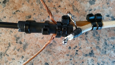
four sides. Once you have a square loop with each side 53.0 cm long you need to terminate the feed point. (See image)
I used good quality cable ties to keep the two ends fixed to the rubber tube. I did insert a 5mm dowel into the rubber tube to make it sturdy and a 8mm wooden dowel to the back of the rubber pipe. (See image) Once I was satisfied with the loop I tighten everything with cable ties. I am sure there is a better way to do this, but this works for me. I will however revert to a better way of attaching the 75 ohm matching stub to the driven element in future. I then soldered the inner and outer each of the RG6U to the copper ends of the driven element and the other end to a short piece of RG58C U coax with a PL259 plug.
Constructing the 75 ohm Quarter Wavelength Matching Transformer:
I opted to use the 75 ohm matching method as it is easy to construct and works well. There are other ways to match the antenna but I will discuss them in a future posting. The quarter wavelength matching transformer would be 1/4 of that length multiplied by .83 to compensate for the velocity factor of the 75 ohm RG6U cable. Calculation = 2120mm divided by 4 x .83 = 439mm = 43.9 cm. In this case the stub should be around 43.9cm long. Formula: 306/144.250 = 2120m /4 = 530 x .83 = 439mm = 43.9 cm
RG6/U 75 ohm Coax Velocity Factor = .83 If you use RG59 CU 75 ohm Coax then the Velocity Factor = .67
Keep in mind that those formulas are for ideal conditions like the antenna being mounted outdoors and in the clear so plan on starting long and trimming for resonance. In my case I had to do no trimming/adjusting at all.
Once you soldered the matching stub to the driven element and the piece of 50 ohm cable you can add the driven element to the boom either in a vertical or horizontal polarization configuration. Ensure the distance between the reflector and driven element is 38.5 cm.
Testing and Adjusting:
Assemble the quad antenna and fix it to a non conductive mast. Ensure that the matching cable and feeding cable is routed away from the driver element and that you choose the selected polarity that you are going to operate with. Now ensure that you put the antenna and mast as high up as possible. This antenna works at its optimal when it is high up as possible. (previously mentioned supra.) Ensure that there are no other antennas, wires, metal objects close to the quad antenna to avoid interactivity between the antenna and objects. Once up in the air add your SWR meter between the antenna and radio that you going to use. Ensure that the SWR meter is set to the correct power level. We will first use low power to test. If the meter has a function to select between SWR and reflected POWER then select SWR. Switch on the power supply and the radio. Set the radio to low power if you have such an option. Now press the PTT while observing the SWR Meter. SWR will be reflected. I was lucky enough that I needed no tuning and pruning to get a good SWR. If you followed the exact measurements then you should also have a low SWR. You can then switch the SWR meter to POWER and press the PTT again. The meter now reflect the output power for your radio at low power. If this is correct then you have a fully working antenna. You can also go to high power and use the same method to test the antenna. My high power and SWR was also spot-on and needed no tuning. If you do have a high SWR then there is a few methods that you can use to lower the SWR.
- Move the reflector and director closer to each other or further away from each other and observe if there is a change in SWR.
- You can resize the reflector by increasing or decreasing the size of the reflector.
- Add a matching stub to the reflector also called a reflector tuning stub. (Not going to discuss this here but Google is your friend.)
- Add a trimmer capacitor 6 - 50 pF between 75 ohm match and antenna element. The trimmer is installed to the center wire of the coax. (Google is your friend.)
I found that if you are very accurate with your measurements, build and use the same material described in this article there is no need to tune the antenna at all.
Performance:
I tested the antenna using a link-stick as a mast. The antenna was free of any obstruction, other antennas, wires, interaction with transmitters etc. Performance was as good as expected. Although analytical antenna-pattern, gain or VNA/Analyzer tests have not been conducted, the portable quad displays an excellent front to back ration as well as gain. SWR was great over a wide spectrum of the 2m band. (144 - 146 Mhz) I was able to access all my local repeaters with 2 watts. The furthest being the Riversdale 145.650 Mhz Repeater at a distance of 82.4 km as a bird fly.. (view the images relating to SWR and Power Output)
SWR Measurement: 144.300 Mhz = 1.1:1 SWR / 145.700 = 1.3:1 SWR
Finally: This antenna design provides a compact package for a directional gain antenna ideally suited for portable operation but could also be used as a base antenna for the shack. It can easily be installed in the attic or taken on a SOTA, POTA or a VHF Contest outing. Do not be surprised to hear me on this antenna during the next PEARS VHF/UHF Contest. This antenna surely has many uses. Lookout for future reports on this Blog about this antenna in operation. I am sure that antenna will afford much pleasure!!
Images: ( Click on images for larger view.)
Resources:
Chester S. Bowles AA1EX
Vladan Petrovic YT1VP
R.J. Decesari WA9GDZ/6
M. Lowell N1LO
Gordon S Hoag K2ZS
Christi Grobbelaar ZS4CGR
Johan Terblanche ZS1I


