Thursday, February 27, 2025

Eskom Loadshedding Solutions - Raspberry Pi Router/Modem "Watchdog" Project: Testing Internet Connection (Part 3)


 Image:  ZS1I AllStar Hub, 145.550 Echolink Simplex Link and ZS-Link SVXLink Reflector

With the recent loadshedding experienced I decided to consolidate several projects that were left hanging due to other more urgent projects or the fact that loadshedding was suspended and there was not really a need to finish such projects.  Well this time around I decided to make a list of unfinished projects and whether loadshedding is suspended early, these projects must be finalized irrespective if there are other more urgent projects.  One such project is the Raspberry Pi Router/Modem "Watchdog" Project.  I received requests from fellow radio amateurs to provide more information setting up the "Watchdog" and what was the end result in connecting it to an AllStar node and LTE Modem/Router. Part 1 and Part 2 is available by clicking on the specific part.

What is the project all about?  In short I needed an automated “watchdog”  to tell me if the Internet was up  or down and if  down to automatically connect to the Internet once it is back up and running again especially during and after loadshedding. (power outages)  If it is up then there is no further action to be taken. In Part 3 I will be looking at a few Linux and Setup commands for this project.  Once you finished constructing the "Watchdog" it is time to "wake it up" and getting it to watch the Internet for connection outages or confirm that it is up and running.

Let's first look at our connections that must be made for the "Watchdog" to work correctly.  
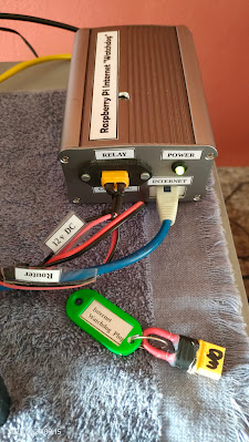
Cables needed:

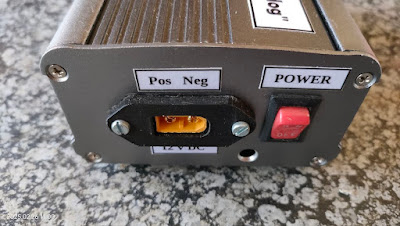
1.  12 v DC Cable to power the "Watchdog"

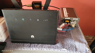
2.  Ethernet Cable coming from the Router/Modem that you will be monitoring.

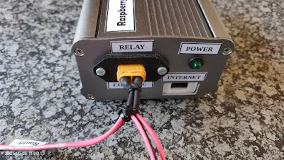
3.  Relay Control Cable.  One end of the cable connects to the Router.  The other end connects to 12v DC going to the Router and the third connection is to the "Watchdog" relay connection which is  Com - NC wired.

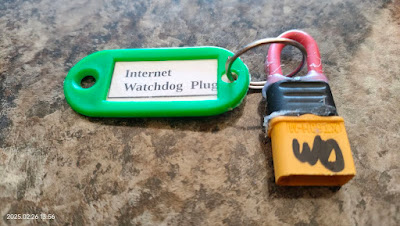
4.  Internet "Watchdog" Bridge Plug -  This is needed when the "Watchdog" is not connected to the Router/Modem.  It is just a wire bridge to give  12 v DC connectivity.

See images for clarity in this regard.

Once you have connected all the cables it is time to switch the unit on.  Wait a few minutes and then retrieve the IP address by either looking in the router/modem or by using software to retrieve the IP address. 

I use VNC to get access to the Raspberry Pi.  Enter  the IP address in VNC as well as your username and password which you must have created when installing the OS.  Once you have logged into the Raspberry Pi you must install Python 3.11.1 if not already installed.  If not installed do a Google search on how to install Python on a Raspberry Pi.  We need Python 3 to run the Internet Watchdog program.  Once Python is installed and you rebooted we need to update the Raspberry Pi.   Open a Terminal window in the Raspberry Pi.

Enter:

$ sudo apt update (enter)

When all the updates are downloaded and installed use clear and enter to clean the terminal window.

We will now write the two script files as shown in Part 2.   Keep Part 2 open in another tab of your browser as we will copy the contents of the two script files into two separate files.  To create each file you will have to follow the procedure listed underneath.

$ sudo su (enter)

$ cd /home/pi (enter)

To create and write a new Python script with Nano:

In the terminal window use:

$ nano filename.py  In our case replace filename with relay_test.py

Copy and paste the relay_test.py in the second browser to relay_test.py  Once copied
press CTRL+S to save the file.
press CTRL+X to exit Nano and come back to the terminal.
Your relay_test.py script file is now created.  Do the same with the relay_final.py script file.  Also open  relay_final.txt and relay_test.txt files by using the above nano method.  Do not copy and paste anything in the relay_final.txt or relay_test.txt files.  Just save them without anything in it.
 
The four files you created will be listed in the /home/pi directory.
You should still be in root@raspberrypi:/home/pi#

Use ls command to list the files.  The files will be listed as:

relay_test.py 
relay_final.py
relay_final.txt
relay_test.txt

Now go to the Applications Menu of the Raspberry Pi (far left top of the screen)
Look for Thonny Python under programming.
Open Thonny
The Thonny Python Program will open 
Click File - Open - select relay_test.py
Click OK
relay_test.py script file will open in Thonny Python
Again click file
Select Open
Click on relay_final.py
Click OK
relay_final.py script file will open in Thonny Python

Time to test if the Internet is UP or DOWN using relay_test.py script

In the Thonny Python Program select relay_test.py  The script has a false IP address to simulate that the Internet is down.

Go to the green round icon with the black triangle pointing  to the right
Click on the icon to run the relay_test.py script
Output will be displayed in Shell (Bottom of Thonny)
 
Output:
 
Date and Time is: 2025-02-24  15:44:12.382124
Testing Internet connection using Ping
PING 1.51.17.1 56(84) bytes of data
(Note the 1.51.17.1 is a fake IP address) to simulate  that the Internet is down)
--- 1.51.17.1 ping statistics ---
5 Packets transmitted, 0 received, 100% packet loss, time 135 ms

1.51.17.1 Internet connection failure
Turning off power to router
Waiting 1 minute to turn router back on
Power up and Reboot router
Nearly there - wait another while!  (Till  >>> appear)

It is clear from the above that we do not have a working Internet connection.  Internet is down!
 
You can replace the IP address in the above script with 8.8.8.8 and again test if the Internet is UP or DOWN.  The output would reflect that the Internet is UP.  No need to change the IP.  We will use the final script to get the "Watchdog" up and running.
 
Next we will use relay_final.py script to find out if the Internet is UP or Down. 

In the Thonny Python Program select relay_final.py 

Go to the green round icon with the black triangle pointing  to the right
Click on the icon to run the relay_final.py script
Output will be displayed in Shell (Bottom of Thonny)
 
Output:
 
Date and Time is 2025-02-24  15:59:35.420916
Testing Internet Connection using Ping
Ping 1.1.1.1 (1.1.1.1) 56 (84) bytes of data
64 bytes from 1.1.1.1; icmp_seq=1 ttl=57 time=66.0ms
64 bytes from 1.1.1.1; icmp_seq=2 ttl=57 time=48.6ms
64 bytes from 1.1.1.1; icmp_seq=3 ttl=57 time=47.4ms
64 bytes from 1.1.1.1; icmp_seq=4 ttl=57 time=48.5ms
64 bytes from 1.1.1.1; icmp_seq=5 ttl=57 time=45.8ms
 
---1.1.1.1 ping statistics ---
5 packets transmitted, 5 received, 0% packet loss, 12 ms
rtt vnin/avg/mox/mdev=45.826/51.277/66.032/7, 446 ms
 
1.1.1.1  Internet connection success.  No further input needed.
 
If the Internet was down the output would be similar to the output we received in relay_test.py simulation.
 
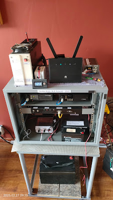
I drilled an inspection hole on the top of the cabinet to view the two LED's on the relay module.  Under normal operation there is a green led that indicates that there is power to the relay module.  There is another relay that will indicate whether the Internet is up or down. (See videos in Part 1)

If only the green power led on the relay module is on then the Internet is up and running.
If the green power led and a red led is lit on the relay module then the Internet is down.

You can now easily see if there is any issues by just looking through the inspection hole.

Finally:  We now need to setup the crontab -e file to run the final script every 10 or 30 minutes (you choose the time interval)
 
Open a Terminal window

Type after $:
crontab -e (enter)
 
Once file open go to the last entry line in the file and enter the following:
 
#*/10 * * * * python3 /home/pi/relay_final.py
#*/2 * * * * python3 /home/pi/relay_final.py >> /home/pi/relay_final.txt 2&>1
#*/2 * * * * python3 /home/pi/relay_test.py
#*/2 * * * * python3 /home/pi/relay_test/py >> /home/pi/relay_test.txt 2&>1
 
We have four options/settings:
 
1.  Running relay_find.py script every 10 minutes
2.  Running relay_find.py script every 2 minutes with output to relay_final.txt file
3.  Running relay_test.py script every 2 minutes
4.  Running relay_test.py script every 2 minutes with output to relay_test.txt file
 
Note:   Options 2 and 4 should not be activated to run continuously as output data can quickly fill up your SD Card.  Just use it for test purposes only.
 
The relay_final.py script will run every 10 minutes and should be activated by removing the # in front of  */10 ------ etc
 
If you go to cd /home/pi (enter) you will see the text (txt) files listed.  If you activated relay_final.py and relay_text.py while testing crontab you can click on the txt file and you will be able to view output when running either script file.  Only run one script txt file at a time.  How ever there is another way to check if crontab ran successfully.

In Terminal use:

grep CRON /var/log/syslog

Note:  After testing script files and txt files ensure that only relay_final.py is activated.  The three other crontab entries should be de-activated by putting an # in front of each entry. 

To check crontab content after closing it you can type in Terminal:

$ crontab -l

Crontab content will be displayed in the terminal window.

This final setup will activate the Raspberry Pi Router "Watchdog" and you will now be able to use this setup/project to automatically monitor the Internet continuously.
 
Enjoy!!


Video:


Images:  Click on images for larger view


Saturday, February 22, 2025

Notifications relating to the SCP ZS-Link Network


Image:  DMR Bridge Dashboard  (Click on image for larger view.)

From time to time it is necessary to notify users of the SCP ZS-Link Network about certain changes/notifications relating to the network.  The following four notifications will be implemented with immediate effect.

Notification No 1:

The DMR Bridge, ZS Link HUB and 145.550 Mhz Simplex Link will be connected full-time to the Aasvoelkop Repeater via ZS1SB-L for the next two weeks. (22/2/2025 - 9/3/2025) 

Start time = 05h55 Monday to Sunday
End time = 20h00 Monday to Sunday

We currently have two radio amateurs visiting Hartenbos and this will enable them to connect to the Aasvoelkop Repeater via the 145.550 Mhz (88.5hz CTCSS Tone) Simplex Link.  We look forward to hearing you on the Aasvoelkop Repeater.   Enjoy the holidays! 

Notification No 2:

1. The DMR Bridge is up and running again after the modem/router decided it had had enough and I couldn't access the modem.  The modem had to be completely "reset" and set up again from factory settings.  Everything is now running as before.

2. The DMR users asked for a "Dashboard" so that they can monitor DMR Activities and also determine whether they are indeed connected to the Bridge.  Well you asked for it and here is the web address of the DMR Bridge in the Southern Cape.

http://dmrbridge.ddns.net/index.php

Notification No 3:

I want to make a request once again that we please pay attention to the gaps between overs on the repeaters as well as the rest of the networks.  If the gaps are too short, fellow radio amateurs cannot connect and disconnect to and from the Network especially when using the DMR Bridge.  Please let's look at the gaps = 6 to 8 Seconds between overs please.  We leave friends out in the cold and then they don't join/connect to us again in the Southern Cape.  We certainly don't want to give anyone the cold shoulder.  

Notification No 4: 

Please keep your overs short when using the Network. (3 min max)  I received several reports that if radio amateurs talk longer that 3 minutes the audio falls away on the DMR Bridge, HUB and 145.550 Mhz Simplex.  The audio only returns when the next person takes an over.  If you are near the 3 minute mark, release the PTT en then carry on and finish your over as soon as possible.  You can talk a lot in 3 minutes.  This will prevent audio falling away on the ZS-Link Network.


Friday, February 21, 2025

Zayn ZR3VO builds a new SHARI PiHat Hotspot for AllStar and Echolink


About a month ago Zayn ZR3VO of Orania decided to put his SHARI HAT together for the Raspberry Pi. Now what is the SHARI PI HAT?

A "Shari PiHat" is a small, self-contained radio interface board designed for amateur radio enthusiasts. 

The SHARI PiHat, developed by folks like N8AR (a known name in the ham community), is a plug-and-play solution for turning a Raspberry Pi into an Allstar node. Allstar, short for Allstar Link, is a VoIP system that connects amateur radio operators worldwide using software like Asterisk. The SHARI PiHat uses the SA818 radio module—a low-cost, embedded VHF/UHF transceiver—combined with a custom circuit board that fits onto the Raspberry Pi’s GPIO pins (hence "PiHat").

Here’s a quick rundown:

Versions: You can get it in VHF (144-148 MHz) or UHF (420-450 MHz), depending on your radio band preference.

Setup: Mount it on a Raspberry Pi, connect an antenna (it often comes with a basic one), plug in a USB cable for audio and power, and load software like HamVoIP (a popular Allstar image for Raspberry Pi).

Function: Once configured, it acts as a simplex node—transmitting and receiving on a single frequency—letting you connect to other nodes or repeaters on the Allstar network.

Power: It’s low-power (around 1 watt), so it’s best for local use or as a hotspot with limited range unless paired with an amplifier.

Construction:  Often sold as a kit, requiring some basic electronics assembly to solder components onto a printed circuit board.

Allstar Network:  To function, the Raspberry Pi needs to be loaded with Allstar software, which enables communication with other Allstar nodes on the network. 

Radio Amateurs use it for things like portable radio nodes, emergency communications, or just experimenting with digital ham radio. It’s DIY-friendly but requires some basic config—like setting your call sign and node number in the software.

I am not going to go into detail about the construction here as the images and video is self explanatory and you can find the complete construction manual by clicking HERE. 

Images:  (Click on images for larger view.)


Sunday, February 16, 2025

100 000 Milestone reached in respect of the ZS Link Network Blog

Image:  Google  (Click on image for larger view)

It gives me great pleasure to announce that the ZS Link Network Blog has reached an all time viewers total (hits) of 100 278 this according to Google.  Is this of any significance?  Well if you like to brag or boast about  the Blog then many will say that this total is on no significance.  Others might be of the opinion that a 100 278 hits can easily be achieved.  Well if the Blog was about South African Politics, Socialites or posting controversial and  inflammatory content then sure you will reach a 100 278 hits in a day or two.  However this blog is about  Amateur Radio/Ham Radio/ Space/Science/Technology/DIY Projects/Homebrew/Nets/AREDN and too many other topics to mention here.  Now why mention this "achievement" here.

It is quite simple.  This Blog is not about the author.  It is about those radio amateurs who contributed direct or indirectly to many posts on this Blog.  You the contributes get all the recognition for keeping this Blog alive and interesting.  Something must be done correctly to reach the 100 000 hits milestone.  I would like to take this opportunity to thank every single radio amateur that contributed to the success of this Blog.  But not only the contributors, also all our readers or visitors from all over the world.  Hopefully in visiting the Blog many of our viewers have find something interesting to read and to view on the Blog.  I could have just kept quiet and say nothing about this milestone but that would be in direct conflict with the amateur radio code, very selfish and ungrateful.

Once again thank you to everyone that contributed to the ZS Link Network Blog in any way.  Lets continue and keep this Blog interesting and relevent.  As of this morning at 09h00 the 100 278 figure has increased to 101 418.

73

Johan ZS1I

Mossel Bay

South Africa

Images:  (Click on images for larger view.)


Tuesday, February 11, 2025

Amateur Radio gees en trots vier hoogty in die Suid Kaap!

Foto:  VHF Dipole geskenk deur Viv ZS1VIV (Klik op foto om te vergroot)

Nou sien ek al die gesigte en opmerkings dat die manne in die Suid Kaap wil nou weer "brag" en wys dat hulle beter is as ander.  As jy daardie gedagte gekry het dan is jy ver verwyderd van hoe 'n groep radio amateurs dinge doen in die Suid Kaap.  Ons is nie ingestel om te spog of aan te dui dat ons beter is as ander radio amateurs nie. Deur so te dink of om te spog bring niks in die sak nie en lei net to verdeeltyd en ook jalosie.  Maar genoeg hiervan.  Waaroor gaan die artikel nou eintlik?

Hier in die Suid Kaap stel die oorgrote meerderheid van radio amateurs nie belang om aan 'n klub te behoort nie.  Nee daar is niks fout om aan 'n klub te behoort nie.  Dit is elke radio amateur se persoonlike keuse.  Daar is egter gevind dat die wyse waarop projekte en aktiwiteite aangepak en uitgevoer word, baie meer suksesvol is wanneer Suid Kaap Radio Amateurs as 'n groep funksioneer.  Daar kan nou geredeneer word dat die groep maar dieselfde funksioneer as 'n klub.  Nee, die redenasie is heeltemal verkeerd.  Maar laat ons nou nie vashak by groep of klub nie.  Die manier waarop die Suid Kaap ZS-Link Groep funksioneer is uniek en iets besonders en daarom ook die suksesse wat reeds behaal is.

As die gees reg is in Amateur Radio en onder radio amateurs dan kan mens letterlik berge versit.  Kyk maar so bietjie terug op die Blog wat die groep die afgelope twee jaar vermag het en hoeveel nuwe radio amateurs tot die stokperdjie in die Suid Kaap toegevoeg is.

Siende dat die artikel handel oor amateur radio gees wat hoogty vier wil ons van die geleentheid gebruik maak as groep om weereens die volgende persone te bedank vir gratis skenkings wat hulle gemaak het om amateur radio te bevorder en verder uit te brei in die Suid Kaap en ook na dele van Suid Afrika.

Skenkings en Donasies:

1.  Name van donateurs verskyn hieronder, maar daar is ook anonieme skenkers wat toerusting en kontant geskenk het.  Aan al ons anonieme en nie genoemde skenkers wil ons baie dankie se vir julle donasies en skenkings.  Julle weet wie julle is.  Baie dankie!!

2.  Dolf  ZS1DRP en Rassie ZS1RP -  Herhaler Toerusting, Sonpaneel  en ander toerusting.

3.  Johann ZS1AAC - Te veel skenkings om op te noem.  Aankope van herhaler benodighede ens. ens. ens.  

4.  Vivian ZS1VIV -  VHF 4 Stack Antenna.  LM400 Koaksiale Kabel en Koppel Stukke

5.  Daniel ZS3DS - VHF Duplexer Filter

6.  Nick ZS1NS - UHF Stainless Steel Yagi Antenna

7.  Johannes ZS1XR - Beskikbaarstelling en gebruik van sy uitstekende koaxiale en koppel stuk krimper tydens die opgradeing van die Stilbaai Herhaler.

8.  Anoniem  -  2 x UHF Motorola GM360 Link Radios en 1 x UHF Notch Filter

9.  Jimmy ZS1RB - 1 x Icom UHF Herhaler

10.  Diegene nie hier genoem nie.  Nee, dit is nie met opset nie. Elke bydrae hoe klein ook al is kosbaar en is ons dankbaar daarvoor maar onthou die ou geheue laat mens partykeer maar in die steek.  Verskoning as jou naam nie genoem is nie.  Stuur gerus die besonderhede dan sal ek dit byvoeg.

As daar mooi gekyk word dan sal julle opmerk dat die toerusting geskenk etlike duisende rande beloop.  Sonder hierdie skenkings sou dit nie moontlik wees om opradering en instandhouding werk te onderneem nie.  Onthou ons is nie 'n klub met 'n ledetal inkomste nie.  As toerusting benodig word dan moet daar 'n manier gevind word om dit te bekom sonder om die las op een of twee persone te plaas.  Wel dit is met groot dankbaarheid dat ons kan berig dat tot dusver skenkings en donasies die "gate" wat onstaan het kon vul.  In dieselfde asem moet on noem dat daar vorentoe toerusting benodig sal word, maar ons weet dat daardie toerusting wel hul "verskyning" sal maak wanneer nodig.

Ten slotte:  Die trots en aansteekbare gees onder radio amateurs wat betrokke is by die Suid Kaap ZS Link Netwerk is iets wat nie misgekyk kan word nie.  Kom ons bou voort op dit wat ons reeds bereik het en dit wat beplan word vir die toekoms tov amateur radio.  Nee ons praat nie net hier van die Suid Kaap Radio Amateurs nie want sien daar is talle radio amateurs in ander dele van Suid Afrika wat voltyds deel is van die Suid Kaap ZS Link Netwerk Groep.  Te veel om hier op te noem.  Met hulle ondersteuning en inskakeling dra hulle by tot die sukses verhaal wat tans afspeel.  Indien daar radio amateurs is wat by ons wil  skakel is hulle baie welkom om deel te vorm van die ZS Link Netwerk Groep.  Ons is nie 'n geslote of uitgesoekte groep nie.  Ons streef die Amateur Radio Kode ten alle tye na en dra dit ook by tot die sukses van die groep.

Monday, February 10, 2025

Revisit the 2m Oblong (rectangular loop) Antenna


(Click on image for larger view.)

In a previous article available HERE I described the construction of The 2m Oblong (rectangular loop) Antenna.  I decided to revisit this very easy to construct antenna.  This antenna is a very popular antenna in parts of Australia and is mainly used for SOTA.  It is easy to make, light to carry and packs small. It is horizontally polarised. (Note: Repeaters use vertical polarization.) The Oblong Antenna I constructed resulted in the following NanoVNA readings:

144.000 Mhz  60 Ohm  VSWR  1.2

145.000 Mhz  53 Ohm  VSWR  1.0

146.000 Mhz  51 Ohm  VSWR  1.0

From the above it is clear that the antenna needed to be lengthened if you want to lower the resonant frequency. However I am more than satisfied with the resonance frequency of the antenna I built and will leave it just the way it is.

An RF Choke is not a bad idea to keep the RF at the antenna.  If required wind 8 turns of RG58AU coax around a 25 mm former. Make a 1 turn loop near the feed point for strain relief on the coax BNC plug.

Testing:  

I once again tested this antenna using my trusted UV82 radio and could access all the local repeaters in the George / Mossel Bay area with three watt output.  I was not able to access the Aasvoelkop Repeater from my QTH using 3 Watts output power. Remember this antenna is horizontally polarized while the repeaters are all vertical polarized.   Polarization clearly played a roll in this regard.  Maybe I will change the polarization in the future just to see if I can access the Aasvoelkop Repeater with this antenna. Remember horizontal polarization has less RF attenuation than vertical polarization at the same output power level.

Final Comment:  

This antenna will be great for HOTA, SOTA, POTA and even Emergency Communications.  Although it does not have gain like a Yagi or a Quad Antenna it is ideal for a cheap, quick, light weight and minimal setup.   Distances of between 60 and 94 km has already been achieved using this antenna in difficult terrain.  

Note:  This antenna is mainly for use on SSB and CW.

Images (Click on images for larger view.)


Sunday, February 9, 2025

Let's build a 2 Meter Portable Handheld RX and TX Antenna to receive great SSTV Images from the ISS


First some background information regarding reception of SSTV Images from the ISS (International Space Station).  I use the SSTV Experiments to test different 2m Handheld Portable Antennas to see which antenna provides the clearest SSTV Images transmitted from the ISS.  My test setup is simple.  Baofeng UV82 HT Radio, Short CoAx Cable, Cellphone with Robot36 and a "homebrew" handheld portable antenna.  No other equipment like a tri-pod, writing board, recorders etc.  A KISS (keep it simple stupid) setup.  No frills no fuzz!

I have tested a few antennas during past SSTV Experiments.  Here are the list:

1.  Homebrew Copper Pipe Upside Down 2 Element Quad Antenna.  (I used this antenna to receive WX Images from satellites)

2.  Homebrew  2m Quarter Wave Antenna.

3.  Homebrew DK7ZB-Duoband-Dipole for 2m/70cm Antenna

4.  Homebrew ZS2U 2 Element 2m Yagi Antenna  ( Second best results thus far)

5.  Homebrew 2 Element 2m Quad Antenna

6.  Diamond X50 2m Antenna

7.  Homebrew 2m Flower Pot Antenna

8.  Homebrew 2m Dipole Antenna (Best results thus far)

For the purpose of this article we are going to build the 2m Dipole Antenna. (Best results)  It is cheap and easy to build and out-performs all other antennas mentioned above. I am not going to go into the theoretical side of this antenna. I am sure you can find information on this dipole antenna using a search engine if you want more information iro 2m Dipole Antennas.

You will need:

Material:

1.2m x 20mm PVC Conduit Pipe

2 x T-Piece PVC Coupler

2 x 500mm x 16mm Aluminum Pipe 

1 x 100 mm x 12mm Wooden Dowl

4 x 14mm x 4mm Self Tapping Screws

2 x 4m Electrical Lugs (Heavy Duty)

1 x 1.5m RG58CU CoAx Cable (2m if you going to wind the coax coil)

1 x PL259 Connector 

1 x Ferrite Clamp (See images) or wind 8 turns of RG58Cu on a 25mm PVC Pipe (85 mm long)

6 x 15mm Cable Ties 

30 mm Piece of Soldering Wire

2 x 13mm Plastic End Caps to cover aluminum pipe holes

Tools Needed:

Pipe Cutter or PVC Cutter.  Hacksaw will also work.

Marker Pen

Round File

Measuring Tape

Screw Drivers (Flat + Star)

Glue Epoxy

Pliers

Soldering Iron

Lug Crimping Tool

PVC Cement (optional)

Insulation Tape

Silicon Sealant

Test Equipment:

VHF SWR Meter

NanoVNA (Optional)

VHF Radio (HT or Mobile)

Coax Patch Leads

Mast (Non conductive)

Coax feed line cable  5 - 10m  RG58CU 50 ohm

Power Supply for Radio

Constructing the Antenna:

Construction is straight forward.  The attached images will assist you in constructing the antenna.  I might just mention that you need to cut two 20mm PVC pieces (each 25mm long) of pipe to fit into the top openings of the T-Connector. You might glue them into place with PVC cement.  The 16mm aluminum pipe will now fit into the T-Piece.  But before you glue anything first use the round file and file the inside of the T-Piece so that the 16mm aluminum will go in all the way to the inspection hole.  Leave the bottom connecting point of the T-Piece unchanged.

A word on the RF Coil (See image below)  If you want to use the antenna for TX and RX,  I would suggest that you add a Ferrite Clamp (See images) or wind 8 turns of RG58Cu on a 25mm PVC Pipe. (85 mm long) This will sent RF to the antenna and not down he coax line back to the radio.

Note:  The length of the dipole element is 1000mm  /  2 = 500mm (each element).  Yes I know this is "unconventional" as normally this length is used for many Yagi antenna reflectors.  In other words if you go by the book the two elements are to long. This is also reflected in the NanoVNA measurements. Be as it may the "proof is in the pudding" that this antenna work great on receiving SSTV images from the ISS.  Even at this length one can still use the dipole for transmitting as the SWR is well within the limits.

Testing and Adjusting the Antenna:

After you assembled the antenna, fix it to a non conductive mast.  Ensure that the matching cable and feeding cable is routed away from the driver elements and that you choose the selected polarity that you are going to operate with.  Now ensure that you put the antenna and mast as high up as possible.   Ensure that there are no other antennas, wires, metal objects close to the antenna to avoid interactivity between the antenna and objects.  Once up in the air add your SWR meter between the antenna and radio that you going to use.  Ensure that the SWR meter is set to the correct power level.   We will first use low power to test. If the meter has a function to select between SWR and reflected POWER then select SWR.  Switch on the power supply and the radio. Set the radio to low power if you have such an option.  Now press the PTT while observing the SWR Meter.  SWR will be reflected.  I was lucky enough that I needed no tuning and pruning to get a good SWR.  If you followed the exact measurements then you should also have a fairly low SWR.  You can then switch the SWR meter to POWER and press the PTT again.  The meter now reflect the output power for your radio at low power.  If this is correct then you have a fully working antenna.  You can also go to high power and use the same method to test the antenna.  My high power and SWR was also spot-on and needed no tuning.  If you have a NanoVNA now is the time to put it to good use.  I use both test instruments.

Performance:

I tested the antenna during a real-time pass of the ISS in receiving SSTV Images.  The antenna was held in the hand and the ISS was "followed" as it passed over my area.  The antenna was not always free of any obstruction, like trees, buildings etc.  Some passes would result in clear images being downloaded while others would have some reception interference visible. Performance was as good as expected in my area.  Maybe next time I will go to a park that has no obstructions.

Finally:  
 
This antenna design provides a compact package for receiving SSTV Images and this antenna is ideally suited for portable operation.  A further plus is this antenna is cheep to build and lightweight to hold in the hand.  This antenna surely has many uses.  Lookout for future reports on this Blog about this antenna in operation.  I am sure that this antenna will afford you much pleasure in downloading clear images!!  Up to now this is the best handheld portable antenna I tested to download SSTV Images from the ISS.

Images:  (Click on images for larger view.)


Here is two SSTV Images I downloaded with this portable antenna holding it in my hand:


Eskom Loadshedding Solutions - Raspberry Pi Router/Modem "Watchdog" Project: Testing Internet Connection (Part 3)

 Image:  ZS1I AllStar Hub, 145.550 Echolink Simplex Link and ZS-Link SVXLink Reflector With the recent loadshedding experienced I decided to...