With the above antenna I worked 38 countries and 129 grids. Only problem
is where do you find a VW Beetle gearbox to construct this antenna? I
was lucky to find one and the above results speak for itself. Apart from the VW Beetle gearbox for this antenna to work you need to have a Toyota Hilux double cab
bakkie in close proximity. View the photo section for the setup. Jokes aside lets build this great antenna!!
The Full-Wave Delta Loop at Low Height.
PLEASE NOTE THIS DESIGN IS NOT MINE. ALL CREDIT GOES TO THE LATE DOUG DeMAW. W1FB (PDF File available HERE)
With the 10m band once again active nowadays why not build this 10m Delta Loop HF Antenna? Interested read on.
Property size and antenna-support height are ever present concerns of the urban radio amateur. Many good antennas are untried because the radio amateur is unable to imagine how a large wire antenna could be squeezed into a small lot. Certainly, this is typical in the case of full-wave loop antennas. But, there is no rule that dictates using a symmetrical loop. It can be distorted rather severely without spoiling the performance. The same philosophy is appropriate with regard to height above ground and the plane in which the antenna is erected. In most instances, a less-than-optimum full wave loop will outperform a dipole or inverted V antenna that is close to ground in terms of wavelength. It is possible that such a loop will give comparatable or better performance than a vertical antenna that is less than 90 degrees (with respect to ground), or one with a substandard ground screen.
We want to discuss the practical construction of this loop that can be supported from low supports on small pieces of property. The results we have obtained are noteworthy with respect to all-around "solid" communications within and outside South Africa. Perhaps you will be inspired to unroll some wire and try a loop at you QTH.
I will not go into all the various configurations for a full wave Delta loop. Radiation angles and polarization are affected by the feed-point placement and location of the apex. Feed point selection will permit the choice of vertical or horizontal polarization. I opted for the apex up with a corner feed which gives me vertical polarization with a low radiation angle, ideal for working DX. It should be said that most DX antennas for HF work are horizontally polarized. The corner feed provides a mix of both horizontal and vertical polarization. Feeding in the centre of the horizontal section will provide primarily horizontal polarization resulting in higher gain at low angles if the bottom is a reasonable height above ground, at least 1/2 wavelength.
You need not use an equilateral triangle if it will not fit on your property. Erect whatever you can, then give it a try.
The matching Q section consists of a quarter wavelength of 75 Ohm, RG59/U coax. The forumula for the loop length is L (feet) = 1005/f (Mhz). For the design frequency I used 28.076. After rounding it off, this yields a loop length of 10.9 meters.
The Q section formula is L (feet) = 246 x V/f (Mhz), where V is the velocity factor of the RG-59 U. The Q section length is 1.763 meters.
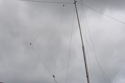
The loop are supported at the top of the mast by a U clamp bolted to a short piece of pipe. An ultraviolet resistant rope with a length twice the mast height is passed through the U clamp to raise and lower the loop.
Materials:
I used the following material to construct the 10m Delta loop:
1. 12m x Electrical copper earth wire
2. 3 x Plastic isolators (bought from the local Co-Op)
3. 2 x brass screws with 4 nuts.
4. 3 x times electrical lugs
5. 1.8m x RG59 C/U 75 Ohm cable
6. 2 40mm End Caps
7. 1 150mm 40mm PVC pipe
8. 1 x SO239 Connector
9. 35m Nylon rope
10. Length of Coax to shack
11. Piece of solder
12. PVC Weld (Glue)
Construction and Testing:
Need I really explain how to construct the antenna? Cut the copper wire longer that the required 10.9 meters. I suggest about 11 meters Slide the 3 x plastic isolators into this length of wire. Now create a triangle. Ensure that your isolators can slide freely. The top of the triangle will go to the top of the tower. The left corner will be tied to one end on the ground while the other corner will be used to attach the Q section. Add two lugs at each end of the loop and solder the ends.
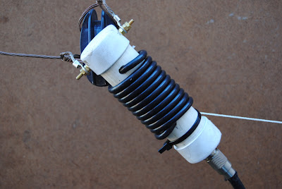
Now we will construct the Q section. Many builders use different types of Q sections but I decided to roll my own. I opted to wind the RG59C/U on a piece of 40mm PVC pipe, embed it's points inside the pipe. At one end the SO239 was attached while at the other end i used two lugs that is fixed to the brass screws and embedded in the PVC cap. Nothing funny just some cosmetics. The Q sections length must be 1.763m long from end to end. My antenna was calculated to resonate on 28076.00 Mhz. Now attach the two lugs on the antenna to the Q section. ("False Balun") I used two cable ties to attach the "False Balun" to the isolator and nylon rope to prevent drag on the feeding point. That's it you now have a Delta loop antenna but it might be necessary to do some trimming or adding copper wire to get a low SWR if you not using an antenna tuner. The antenna I build reflected an SWR of 1:5 and my radio is quite happy with the antenna. I did some further tests and found that the antenna I constructed resonates at 29000.00 MHZ with and SWR of 1:1. So the antenna length must be increased if I want it to resonate say at 28200.00 Mhz. I did not bother.
Final Assembly:
Final assembly as per photographs below.
Using the Antenna:
The Delta loop is a directional antenna, like a simple beam, giving best performance when the loop is facing the station you wish to contact or hear. This makes it ideal for "pointing" at a favorite direction, such as Europe, Asia or the Pacific. I was able to point the Delta Loop in the most effective direction but can also steer the antenna in other directions if I so wish. I was amazed to find that this simple steering of the antenna, made all the difference, firstly to reception and then transmission. It regularly produced signals in the wanted direction.
I hope that you will try this amazing antenna, which, using the formulae given can be quickly made for almost any band that interests you.
One final tip, if you are using ordinary stranded electrical wire, it will stretch after a week or so, under its own weight and mainly due to the weight of the matching "balun". This will cause the antenna to work better lower than the original center frequency.
This is not a problem, all you do is lower the antenna, re measure it and cut to size.
Results:
First time use netted the following DX stations.
LU1FNR, R3MO,RX6ATA, LU7WWW, LU3HR, ES3BR, UA3ZJC, RW4HBG,LU9HQS, UX7MX, UR5XBM, DL2ROE, OK1TQ, PY2DNR, DL8DXF, DL6SDA, W9OL, IW1FLR, LU1BR, YU2MBM, MM0GZZ, OE6KD AND LU2DNK.
These stations were worked with the antenna installed at the test setup position, that is with the VW gearbox and Hilux in place and with the antenna only 1.5 meter from the ground. Myself and Johan ZS2I could not believe the performance of this antenna and we decided that all the objects around this antenna was the reason why this antenna work so great. I have since moved the antenna to it's permanent position on my aluminum mast and still work the world with this gem of an antenna.
Performance:
The logbook speaks for this antenna. From the 30 March 2011 to 30 April 2011 I worked 46 47 countries, 175182 grids and made 268 293 contacts on the 10 meter band. Not to bad for a piece of wire in the air.
I get great pleasure out of this antenna. Why not build this antenna and join me and others on the 10m Band?
Photos:
(Click on images for larger view.)


