Saturday, November 30, 2024

Hoe saai ek Sondae die Bo Karoo Amateur Radio Klub se Nuusbulletin uit hier vanaf die Suid Kaap?


Nou ja dit is vandag Sondag en ek het so pas die klank ("audio") bulletin van die Bo Karoo Amateur Radio Klub (ZR3VDK) hier vanaf Mossel Baai uitgesaai.  Vir my is dat al tweede natuur aangesien ek dit reeds vir die afgelope paar jaar doen.  Ek is nie n lid van die Bo Karoo Klub nie en doen dit absoluut op 'n vrywillige basis.  So saai ek ook ander bulletins uit selfs Intenasionale Bulletins.  Nee, ek spog nie hier of probeer nie om die aandag op my te vestig nie.  Jy hoef mos nie 'n lid te wees van enige klub om die stokperdjie te bevorder of 'n bydrae te lewer van watter aard ook al nie.  Nou wat se ek nou eintlik hier.  Jy kan nogsteeds enige klub of organisasie van hulp wees al is jy nie betrokke by die klub nie. Die klein bydra wat ek lewer is om Amateur Radio te bevorder en veral die nuwe radio amateurs van hulp te wees.  Genoeg hiervan laat ons tot die punt kom. 

Hoe saai ek die audio bulletin uit van die Bo Karoo Amateur Radio Klub op die ZS - Link Hub Netwerk in die Suid Kaap?  Dit is eintlik heel eenvoudig.  Verby is die dae van  koppelstukke (Patchboxes) of direkte lewendige uitsendings.  In die artikel gaan ek verduidelik van hoe maklik dit is.  Nou daar is verskeie maniere om dit te doen.  Die oorsese bulletins word alles automaties behartig.  'n Half uur voor die uitsending word die bulletin outomaties deur die Raspberry Pi  wat die Hub Netwerk bedryf afgelaai en dan verwerk.  Die bulletin word in 6 of 7 dele "opgebreek" in tussen poses om herhalers en netwerk die geleentheid te gee om te herstel (te reset).  Ek gaan nie die hele proses verduidelik nie, maar alles insluitende die aankondigings en uitsending word outomaties gedoen. (Natuurlik onder my direkte toesig van enige plek in die wereld.)

Wat benodig ek om die audio uitsending van ZR3VDK te behartig?  Voor ek die lys verskaf wil ek net noem dat 99% van radio amateurs reeds oor die nodige toerusting beskik om so 'n uitsending te behartig.  

1.  Windows Rekenaar (Windows 7, Klank Kaart en Luidsprekers)
2.  Internet Koppeling  (Enige tipe)

Vir die doeneindes van die artikel gaan ek nie in diepte die installering van sagteware bespreek nie.  Dit is beskikbaar wanneer u die sagteware aflaai vanaf die verskafte skakels.  Ek sal egter hier en daar verwys waar daar moontlik onduidelik mag wees.
 

Hoe doen ek dit?

Punt 1 en 2 is selfverduidelikend en meeste radio amateurs het 'n rekenaar reeds in die amateur radio kamer. As jy nie reeds Echolink op jou rekenaar geinstalleer het nie kan jy die sagteware aflaai en installeer soos verduidelik word op Echolink se webblad.  Maak seker dat Echolink korrek werk en dat jy kan koppel aan stasies, hulle jou kan ontvang as jy PTT en dat jy hulle kan ontvang  maw Echolink moet volwaardig werk. As jou Echolink nie reg werk nie moet jy dit eers maak werk.  Vra hulp en raad maar die Echolink Handleiding is baie volledig. Onthou om die drie poorte (5198,5199 en 5200 te "Port Forward" in jou Internet Modem/Router)  Met Echolink in 'n werkende toestand is dit nou tyd om die Audacity sagteware te installeer.  Wat is Audacity?  Audacity is die wêreld se gewildste gratis sagteware om klank (audio) op te neem te redigeer en terug te speel.  Weereens Audacity het 'n goeie handleiding en behoort daar nie probleme te wees om die sagteware te installeer nie.
 
Nota:  As jy Audacity geinstalleer het moet jy die klankkaart selekteer. Kyk net onder die "Taskbar" in Audacity.  Jy sal 'n mikrofoon- en luidspreker kenteken sien.  Hier kan jy jou mikrofoon en luidspreker vir die klankkaart wat jy gebruik selekteer.  Gewoonlik interne klankaart of USB Klankaart.  Jy moet 'n opname kan maak en dit dan terugspeel oor die rekenaar se luidsprekers.  Weereens jy kan nie voortgaan met die installasie van Voice Meeter Banana Sagteware as Audacity nie korrek funksioneer nie.


Nou is dit Voice Meeter Banana se beurt.  Die sagteware mag intimiderend voorkom maar as jy nie orals gaan krap nie is dit eintlik heel eenvoudig om dit aan die gang te kry.  Ek gaan so paar kriptiese punte hieronder verskaf.

VBAN moet afgeskakel wees.  Klik op VBAN aan die regterkant bo van die program.  'n Skerm sal open en VBAN behoort afgeskakel te wees.  As hy aan is (blou kleur) klik net op VBAN IS ON om dit af te skakel.
 
"HARDWARE INPUT 1"
 
Klik op "Hardware Input 1" en skerm sal open waar jy jou klank kaart inset kan selekteer. Bv.
Select:  "MME: Microphone (USB PNP Audio)"  Klik om te selekteer.
Beweeg af na "Fader Gain" en skuif dit na  0dB.  Klik op A1 en B2.  Sal groen vertoon soos in foto hierbo.
Beweeg nou na "Hardware Input 2 en 3" en klik op "Mute".  Sal na rooi verander  Die inputs gaan ons nie gebruik nie.
Beweeg nou na "Virtual Inputs" - Voicemeeter VAIO en AUX moet geselekteer work.  Verwys na handleiding in die verband.
Jy kan nou vestellings maak aan die "Equilizer" settings links en regs.  Verwys na handleiding.
"Fader Gain" soos in foto hierbo.
Klik A1 en B1 links en A1 en B2 regs
 
"HARDWARE OUT en MASTER SECTION"
 
Die "Input" kant is nou reg opgestel.  Kom ons kyk nou na die "Hardware Out" en "Master Section".
Klik op A1 blok
Select: "MME: Speakers (USB PNP Audio/Sound Device)"  Klik om te selekteer.
In die "Master Section"
Klik selekteer "Normal Mode, Mono, EQ en Fader Gain" soos in foto hierbo.
Al die ander sliders soos in die foto hierbo.

Nota:  Raadpleeg die Voice Meeter Banana handleiding sou jy probleme ondervind.  Onthou die foto hierbo is hoe ek VoiceMeeter opgestel het vir die tipe toerusting wat ek gebruik.

Die Sagteware Installasies is nou voltooi.  Maar hoe gaan mens nou te werk om die sagteware te laat "saampraat" om 'n klank bulletin uit te saai.

Hier is die volgorde wat ek gebruik:

Voordat enige uitsendings gedoen word is dit altyd 'n goeie praktyk om die rekenaar te "reboot".  Nadat die rekenaar ge-"reboot" het gaan ons heel eerste op die Voice Meeter Banana "icon" klik.  Jy sal sien dat tydens die opening toets VoiceMeeter of die regte klankaart geselekteer is.  As daar geen waarskuwings  skerms verskyn nie weet ons dat die Rekenaar en VoiceMeeter "saam gesels".

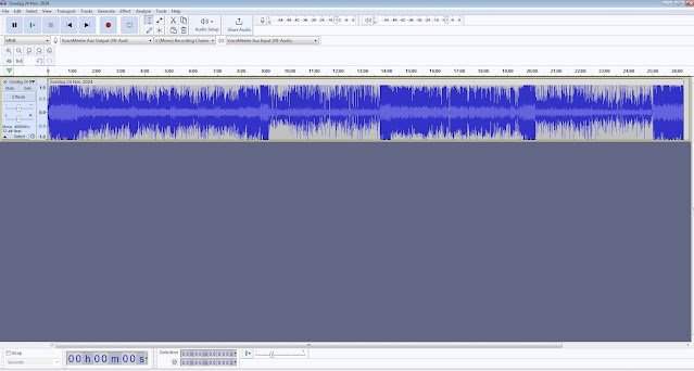
Nou klik ons op die Audacity "icon". Nadat Audacity klaar gelaai het maak seker dat "MME (Mic) VoiceMeeter Aux Output (VB Audio) en  1 (Mono Recording Channel (VB Audio) en Voice-Meeter Aux Input (VB Audio)" geselekteer is. As daar geen waarskuwing skerms verskyn nie weet ons dat die Rekenaar, VoiceMeeter en Audacity nou "saam gesels".

Nou moet ons die audio formaat opstel wat Audacity gaan gebruik. (OGG, WAVE, MP3 etc.)  Vir die doel gaan ons FFMpeg installeer.  Alles wat jy nodig het om dit te doen is HIER beskikbaar.  Daar is selfs 'n video hoe om dit te installeer en op te stel.  Ons benodig FFMpeg om die OGG formaat te verander anders sal Audacity nie die OGG formaat toelaat nie.  Nadat die installasie gedoen is behoort Audacity die audio file te laai en te speel.

"Reboot" nou weer die rekenaar en dan gaan ons die Bulletin laai.  Onthou maak VoiceMeeter eerste oop en dan Audacity.  In Audacity klik op File, Import, Audio en kies die Bulletin leer wat gelaai moet word.  Die Bulletin leer sal open en jy kan dit dan edit sou jy wou en as jy weet hoe.
Anders los hom net so.
 

Nou is dit tyd om Echolink oop te maak waarmee ons die Bulletin gaan uitsaak.  Koppel aan een van die Echolink stasies waar jy die bulletin gaan uitsaai.  Met VoiceMeeter, Audacity en Echolink oop is dit nou tyd dat ons die bulletin uitsaai.  Die levels in VoiceMeeter is reeds opgestel.  In Audacity moet ons nou die "PLAY" knoppie klik en dan dadelik op "Transmit" in Echolink.  Die bulletin sal dan begin en jy kan daarna luister op jou rekenaar of radio.  As die bulletin klaar gespeel het dan moet jy weer op die "Transmit" knoppie klik om Echolink te stop en die uitsending.  Maak ook seker dat Audacity gestop het.  Dan kan jy Audacity toemaak en op Echolink gesels of na bulletin inroepe hanteer.

Dit is hoe ek die Bo Karoo Amateur Radio Klub se nuusbulletin uitsaai. Jy kan ook die nodige audio vestellings via VoiceMeeter Banana doen soos nodig.  Waarskuwing:  Lees maar eers die VoiceMeeter handleiding voordat jy verstellings maak.

Ek vertrou dat daar na die plasing van die artikel talle nuwe bulletin uitsaaiers na vore sal kom om nuus bulletins uit te saai.  Wonder wie gaan die eerste radio amateur wees wat die stelsel gaan implimenteer vir die uitsaai van die Bo Karoo Amateur Radio Klub bulletins.  Daar is nou geen meer verskoning waarom bulletins nie professioneel uitgesaai kan word nie.

Thursday, November 28, 2024

An "Outboard" Over Voltage Protection Project for a Power Supply


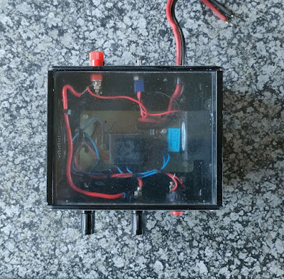
I built this project in February 2004 and it appeared in QSX the monthly newsletter of PEARS.   I decided to give it a decal makeover as the 2004 Letraset decals looked rather old and worst for wear.

I know that there are many articles in the past in QSX relating to the above project.  However after constructing the Heavy Duty Power Supply described by Andre Botes ZS2ACP in QSX I decided to look at the over voltage protection circuitry.

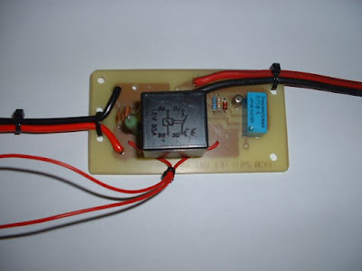
A thought came to mind that a separate PCB that hosts the over voltage protection components could come in handy especially if you have a power supply with no such protection.  I changed the PCB outlay to suit my needs and come up with a board as shown in the image below. (Not to scale)  As this is a simple project, I will  not go into all the detail to construct the protection unit other than providing you with the component overlay and a few photos of the project amongst the images below.

Just a word of advice:  Use thick wire on the input as well as the output side depending on the amount of current (amps) your power supply provides.

This handy little unit could save you a lot of tears and money if your power supply decide to go into over-voltage- or short circuit mode.  

Images:  (Click on images for larger view)

Component List:

    1. Green LED
    2. 1K2 Resistor
    3. Relay 30 AMP AUTO 12 Volt
    4. Relay TAKAMISAWA RY5W-K  5 Volt
    5. Push Button
    6. BC 108 OR BC 109
    7. 1K Resistor
    8. 13V Zener Diode
    9. 10K Resistor
    10. 470 Ohm 5 Watt Resistor
    11. 0.01 Capacitor
    12. 0.0001 Capacitor
    13. 0.1 Capacitor
    14. 470 Ohm Resistor
    15. Red LED


Wednesday, November 27, 2024

"Blits" Besoek aan die Aasvoelkop Herhaler - 24 November 2024


Die afgelope naweek het Johann ZS1AAC, Henry ZS1SB, Eben ZS1EP en Jasper ZS1WT 'n "blits" besoek aan die Aasvoelkop Herhaler (145.625 Mhz, 88.5 hz CTCSS) gemaak.  Meer oor die herhaler is HIER beskikbaar.

Soos baie van julle weet is daar maar altyd herstelwerk en opgraderings wat gemaak moet word aan herhaler installasies.  

Die manne is bergop met al die toerusting en parte wat hulle toe suksesvol geinstalleer het.  Johann ZS1AAC het aangedui dat die installasie op Aasvoelkop nou afgehandel is en dat daar nou gekonsentreer sal word op die Stilbaai Herhaler (145.750 Mhz 88.5 hz CTCSS) en die Anysberg Herhaler.

Tans funksioneer die Aasvoelkop Herhaler goed en word dit goed benut op 'n daaglikse basis met drie net byeenkomste nl:

  • Sonsopkoms Net  (Seevoels groet elke oggend)
  • Ontbytsake Net
  • Sonsakspan Net   (Hadida's groet elke aand)

Verskeie VOIP Netwerke koppel op 'n daaglikse basis aan die Aasvoelkop Echolink Node (ZS1SB-L)

Sluit gerus aan en kom gesels saam.

Laastens maar nie die minste nie, baie dankie aan Johann ZS1AAC, Henry ZS1SB, Eben ZS1EP en Jasper ZS1WT vir die herstelwerk en opgraderings aan die Aasvoelkop Herhaler!

Fotos (Klik op fotos om te vergroot)


Friday, November 22, 2024

Notification: ZS Link Hub Network, Mossel Bay - Upgrading and Maintenance.


KENNISGEWING: 22 November 2024 - Let asseblief daarop dat die ZS Link Hub Netwerk, Mosselbaai vir ‘n groot gedeelte van die dag afgeskakel sal wees vir opgradering en instandhouding. Die volgende stelsels sal nie beskikbaar wees nie:

Echolink ZS1I-R

AllStar 49355

DMR BRUG TG65511

SVXLINK Reflector

APRS Igate

145.550 Mhz Link Radio


NOTICE: 22 November 2024 - Please note that the ZS Link Hub Network, Mossel Bay will be switched off for a large part of the day for upgrading and maintenance. The following systems will be unavailable:

Echolink ZS1I-R

All Star 49355

DMR BRIDGE TG65511

SVXLINK Reflector

APRS Igate

145.550 Mhz Link Radio

Thursday, November 21, 2024

Southern Cape ZS1I SVXLink Reflector Changes and Modifications (Part 1)


Want to know more about the Southern Cape ZS1I SVXReflector?  Click HERE

Awhile back I posted the following in an article: 

"Some time ago I was looking for a UHF Motorola Radio to be used with a SVXLink node.  I put out a request for such a radio and Mark ZS4OIL responded that he has such a radio.  I was unsuccessful in all my efforts to buy the radio from him.  He refused to accept anything even the costs to send the radio to me.  Mark donated a UHF Motorola GM300 radio  to me.   I received the radio this morning.  This radio will be used as a link radio for the ZS1I SVXLink Reflector that is currently connected via VHF to the ZS Link Network here in the Southern Cape.

Mark I would like to thank you for your generosity, great amateur radio spirit and for donating this radio, to be used to extend the ZS Link Network in the Southern Cape.  Highly appreciated and once again a big thank you!!

I will later post images where this radio is connected to the network and operational."

Herewith a few images of the radio attached to the  ZS1I SVXLink Reflector.  Click on images for larger view.


As the title of this topic indicate I made a few changes to the Motorola GM300 UHF Radio and the ZS1I SVXReflector.

Radio Changes:

1.  I programmed two frequencies  =  433.550 Mhz and 433.500 Mhz

2.  The COS Modification was done as illustrated in the image below

3.  RX CTCSS of 88.5 Hz programmed

4.  Remote hook switch modification for RX CTCSS was done

5.  Added Ext. Speaker wire to the 16 pin expanded accessory connector at the back of the radio


These modifications are necessary when using these older type of Motorola radios that does not have the newer logic boards installed.  With the newer Motorola's you can program some of  the output pins on the 16 pin expanded accessory connector.  The radio is now ready to be connected to the SVXLink Reflector Node.

SVXLink Reflector Changes:

1.  During the initial setup I decided to use the GPIOD value for the type of squelch detector.  It was setup in the SVXLink.Conf file under  SQL_DET in the RX1 section.  In the TX1 section PTT_TYPE was set as GPIOD.  Testing the setup without CTCSS worked flawlessly but adding the CTCSS to the mix resulted in either the Motorola or Modified Node not being happy.  Now this modification is not the first I have done relating to this radio.  No matter what I tried it would work fine but when I added CTCSS both units would go completely crazy with all sorts of issues.  I suspect that the modified IRLP Board might have something to do with this.  Be as it may there is always a plan B.

2.  If I do not need to use CTCSS the radio and the node works fine without any issues.  However I found that there are some commercial break-thru in my area and that adding CTCSS is a must.  Now do I replace the current radio or modified IRLP Board with a newer radio and build a new interface board.  This could be used as plan B but I decided to use another type of squelch detector that would allow for the use of CTCSS.  The beauty of SVXLink is that there are many options available.  Possible values are:  VOX (not recommended), CTCSS, SERIAL, EVDEV, SIGLEV, PTY, GPIOD, HIDRAW or a combination of CTCSS and GPIOD.  I decided to set SQL_DET=CTCSS in the Rx1 section and PTT_TYPE=GPIOD  in the Tx1 section.

This is not as easy as just replacing GPIOD with CTCSS for RX1.  To use the CTCSS value one need to make several other changes to the SVXLink.Conf file.  It took me a few days to get the "combinations" correct in order for CTCSS to function properly. 

COS (Carrier Operated Squelch) and CTCSS is used to open receiver control in SVXLink

Let's look at how to enable COS and CTCSS to open the Motorola's receiver in SVXLink Reflector. But first before we look at the method I used to detect the carrier operated squelch the general rule in the construction of a radio link or repeater link in this part of the world is to only use COS and not VOX. A  sub-tone or better known in amateur radio circles as CTCSS must be activated.  CTCSS will not allow the receiver to open due to interference that may occur in the area of the installed radio device. This is a very important when a Radio or Repeater is connected to ANY VOIP- or Radio Network.  With the COS modification already done as per image in the Radio Changes section above we now need to set the SQL_DET parameter in the SVXLink.Conf file under [Rx1].  We also need to make a few other changes that relates to the use of CTCSS.

I chose not to use flat unfiltered audio or setting jumper JU551.  I decided to use SVXLink to receive the incoming CTCSS tone and open the transmitter on receiving the correct CTCSS tone. SVXLink can decode the sub-tone and use it to inform that the COS is active, and that the transmitter will then go into TX.  Sounds easy? Well it is if you know what settings to change to make it work   I made the following changes in SVXLink.Conf under the following heading:

[Rx 1]

(I changed the following and it worked for my setup.)

SQL_DET=CTCSS
SQL_START_DELAY=0
SQL_DELAY=0
SQL_HANGTIME=0
SQL_EXTENDED_HANGTIME=1000
SQL_EXTENDED_HANGTIME_THRESH=15
SQL_TIMEOUT=300
CTCSS_MODE=2
CTCSS_FQ=88.5:1
CTCSS_SNR_OFFSET=0
CTCSS_OPEN_THRESH=12
CTCSS_CLOSE_THRESH=5
CTCSS_BPF_LOW=60
CTCSS_BPF_HIGH=270
DEEMPHASIS=0
PREAMP=0
PEAK_METER=0
DTMF_DEC_TYPE=INTERNAL
DTMF_MUTING=1
DTMF_HANTIME=100

As I mainly use DTMF to do switching between networks the above setup is working with the SVXLink Reflector currently in use.  With regards to transmit (PTT) side of things I use the following setup in SVXLink.Conf file under [Tx1].  This setup is working well and thus far I have not experienced any problems.

[Tx 1]

(I changed the following and it is working for the setup I use.)

PTT_TYPE=GPIOD
PTT_GPIOD_CHIP=gpiochip0
PTT_GPIOD_LINE=17
TX_DELAY=3
PREEMPHASIS=0
 
The GPIOD method is based on the gpiod library and this method is used with the Raspberry Pi and my modified IRLP Board. 

It is important that when "playing" around with the above configuration variables that you consult the SVXLink doc file called SVXLINK.CONF available HERE

To sum up:
 
1.  The necessary Radio Changes and Modifications were made.
2.  Changes were made to the SVXLink Reflector
3.  The changes result in:
  • Opening the squelch in SVXLink when the sub-tone is received
  • PTT activated once the squelch opens
  • Close the squelch when the sub-tone is no longer present
  • Close the squelch also when there is no signal at GPIOD anymore and deactivate the PTT
  • Setting the TXDelay to 3 is working for my setup.  This value might need to be increased to between 500 and 800ms in some cases.  FM radios (Mobile and handheld) need time to open the squelch after a signal appears.  The greater the distance and the weaker the signal, you will need more milliseconds to turn the transmitter on and starting the audio transmission.
     

The use of CTCSS for squelch detect and GPIOD as PTT type is working well with my "unusual" self constructed node. I  have pointed you in the direction of how to use the above setup to get your SVXLink Reflector working with this setup.  I trust that this article will be of use to others.

ED.  In Part 2 I will be explaining how to use the ZS1I SVXLink Reflector and will also provide the benefits of the reflector in general to radio amateurs and the ZS Linked Network.

Tuesday, November 19, 2024

Revisit - DIY MC3423 Overvoltage Crowbar Protection Circuit Project


The original article is available HERE.

This Over-voltage Crowbar Protection unit was running  from April 2024 day and night without any disruptions.  About a week ago I noticed that the ZS Link Hub Network radio was off one morning when I entered the Shack.  The Power Supply was running but there was no life in the "black box" which housed the Crowbar circuitry.  


The first thing I checked was the fuse that normally go up in smoke if the protection circuitry "kicks in".  There was nothing wrong with the fuse.  The next item to check was the BT152 Thyristor.  It tested OK.  Next would be the MC3423.  Replaced it and still no power.  A closer look at the Veroboard revealed that  the output (positive) track to the Motorola radio has lifted from the phenol board.  The copper track was cracked and there was no connectivity.  Well this told me that the Veroboard tacks could not handle the amps drawn from the power supply.  When I constructed the unit this was one of my concerns but I thought that with only the radio connected this would not be an issue.  Continues daily use proved otherwise and the Vero PCB track failed.


According to the original Vero spec the area of a strip is equal to 39g which is rated to carry 2 amps for 1 second before fusing.  Well if this holds true then the Veroboard that I  used lasted surprisingly well.  Fixing the unit was quite easy.  I joined two tracks together for the input and output side and soldered a 2.5 mm solid tinned copper wire on top of the tracks.  This is not optimal but I am sure that it will be able to carry the load and hopefully last longer than the Vero board strip.  In the event that it fails again I will use 3 - 5 mm tinted copper wire to which I will connect the main crowbar low amperage circuit board.  After all the main circuit board only suffice as sensing unit.

After the modification, the board was placed back into the "black box", the wires connected and the unit switched on.  It fired right up.  The Motorola specs shows 7.0 Amps current drawn on TX  @ 25 watts and a standby current of 400 mA.  I am sure that the 2.5 mm copper wire and the added track will be more than enough to handle the necessary current.  Time will tell!

Finally:  I will be playing around with a few other Crowbar Protection-  and Reverse Polarity Circuits.  More on this in future postings.


Sunday, November 17, 2024

Let's Revisit the 2 Meter Two Element VHF Yagi by Albert ZS2U

Albert (Al) Akers ZS2U
 
The article about this small and compact "Sharp Shooter Antenna" was published in the PEARS  QSX News Letter of February 2008 by Al Akers ZS2U.  I constructed it in March 2008 and still has it today.  An article about this antenna was published on this Blog in December 2021 and is available HERE.  (Must read)


My final measurements using 3 mm Brass Brazing Rod were:

Driven Elements: 460 mm

Reflector Element:  1000 mm

Spacing between driven- and reflector element : 445  mm

PVC tubing length: 170 mm

Length of Coax:: 1100 mm 


Now why would one revisit this two element Yagi antenna?  There is currently once again an ARISS Slow Scan Television (SSTV) experiment from the International Space Station under way.  (More information HERE)

I decided to use this antenna to download SSTV images from the ISS.  But will it be any good?  This antenna has a very good track record here in the Southern Cape. I use this antenna as a "test antenna" when the need arises.  It is a practical, compact and fold able antenna.  It performs very well.  In  March 2008 I made the following "record breaking" contacts:

I managed to have a short QSO with Terry ZS2ABB in Port Elizabeth from Mossel Bay. A distance of over 300km. In the second attempt I worked Alex RW1ZC/MM on the 6/3/2008 on 2M Voice 144.400 Mhz Fm. Grid: KF35BP 368.3km again from Mossel Bay. 


Image above:  Did you know that the first contacts from the ARISS radio on the ISS happened on the 13 November 2000.  There were two test transmissions received in Russia and one in USA. The images of those contacts are now being transmitted via SSTV in the current series.

But what will the results be using this antenna to download SSTV images from the ISS?  Well you be the judge.  Here are some images I downloaded.  I specifically looked for "bad" passes with a low elevation level of between 0 - 25 Degrees.  The one image published here had  a maximum elevation of 49 Degrees.  Through the years I tried several homebrew antennas to download SSTV images.  This antenna performs well.  At a later stage I will write an article about the best antenna I used to download SSTV images from my QTH in KF15bt in Mossel Bay, ZA.

Images downloaded on 16 and 17 November 2024:

Submitted by: Johan Terblanche, ZS1I, Africa
Acquired: 2024-11-16 10:03:00

Mission: Expedition 72 - Series 22 Fortieth Anniversary
Minimum ISS Elevation: 10 Deg
Max ISS Elevation: 17.2 Deg
Antenna: Homebrew 2 Element ZS2U Yagi (Portable)
Radio: Baofeng UV82
Remarks: No Antenna Rotator or Auto Tracking used

Submitted by: Johan Terblanche, ZS1I, Select a region
Acquired: 2024-11-16 11:39:00
Mission: Expedition 72 - Series 22 Fortieth Anniversary
Minimum ISS Elevation:  10 Deg
Max ISS Elevation: 49.7 Deg
Antenna:  Homebrew 2 Element ZS2U Yagi (Portable)
Radio:  Baofeng UV82
Remarks: No Antenna Rotator or Auto Tracking used

Submitted by: Johan Terblanche, ZS1I, Select a region
Acquired: 2024-11-17 04:19:00
Mission: Expedition 72 - Series 22 Fortieth Anniversary
Minimum ISS Elevation:  10 Deg
Max ISS Elevation: 22.9 Deg
Antenna:  Homebrew 2 Element ZS2U Yagi (Portable)
Radio:  Baofeng UV82
Remarks: No Antenna Rotator or Auto Tracking used

In my opinion not to bad image downloads with a two element homebrew portable Yagi antenna.  I will download two more passes with this antenna and then switch to another portable antenna.

How versatile is this antenna really?   In my opinion a really versatile antenna and can be used for the following purposes:

1.  2m DX Long Distance Contacts
2.  Download SSTV images from ISS
3.  Satellite Contacts
4.  Foxhunting
5.  Interference Tracking Antenna 
6.  Baofeng Radio Distance Experiment  (ZS6 Region)
7.  Demonstrating Amateur Radio Communications
8.  Repeater accessing antenna

To mention just a few.

Other interesting aspects of this "Sharp Shooting" Antenna:

1.  Low cost to construct
2.  Easy construction with available hand tools
3.  Low profile when folded into parts (see image)
4.  Easy storage
5.  Vertical and Horizontal polarization by just turning the two elements by hand
6.  No large mast required but can be mounted on a tower or mast.
7.  Hand operated.  (No rotator necessary)
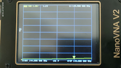
8.  Gain:  4 to 5 dB (Not officially confirmed) SWR:  1:1
9.  Elements can be constructed with Aluminium Wire, Copper Wire,  Coat Hanger Wire, 7 mm Aluminum Rod, 12 mm Aluminum Tubing, 3 mm Aluminium Brazing Rod or 3 mm Brass Brazing Rod. (Brass Brazing Rod Preferred)
10.  Can be used as a Half Wave Dipole by just using the driven element.  (Omitting the reflector element.)

This proved that this “little” antenna is worthwhile constructing and is a real asset to my antenna arsenal.

So what are you waiting for get to your nearest hardware supply store and gather the necessary hardware to construct this antenna. You will be amazed at it's performance!!

Many thanks to Albert ZS2U for making this antenna project available for homebrew construction.

Images:  Click on images for larger view.

Image: ZS1I operating position for the current series of SSTV images

Image:  The 2 Meter Two Element VHF Yagi dismantled for storage or transport

Monday, November 11, 2024

Lest we Forget !!


November is a time that all veterans reflect on the past.  A month that we stand in silence and pay our respects to the fallen soldiers.  Does not matter if that soldier once was your enemy.  He or she only fought in a war that was started by men that never saw the battlefield, the blood, the carnage, the fear, the tears and the heart ache.

When we stand with bowed heads on the 11th hour of the 11th month on Remembrance Day, we don't just pay respect to the fallen but we also celebrate life.  We are still alive and that gives us the opportunity to give out fallen brothers and sisters a salute.

In South Africa, Remembrance Day Commemoration ceremonies are usually held on the nearest Sunday, at which the "Last Post" is played by a bugler followed by the observation of a two-minute silence. Ceremonies to mark the event in South Africa are held at the Cenotaph in Cape Town, and in Pretoria at the Voortrekker Monument cenotaph, the War Memorial at the Union Buildings and other cities and towns.  Remembrance Day services is held to honor those who died in the two World Wars and the Border War. 

Remembrance Day is a national opportunity to remember the service and sacrifice of all those that have defended our freedoms and protected our way of life.

We remember the Armed Forces, their families and the vital role played by those who have lost their lives as a result of war.


“They shall grow not old, as we that are left grow old:
Age shall not weary them, nor the years condemn.
At the going down of the sun and in the morning,
We will remember them.”
― Laurence Binyon
 

The Last Post ( Courtesy: Music Files Limited)

 
Listen HERE

Sunday, November 10, 2024

Decoding SSTV Images from the ISS with a "Homebrew" Antenna. By Rulhof ZS4RM

The recent ARISS Slow Scan Television (SSTV) experiment from the International Space Station took place from Tuesday, October 8, at 16:00 GMT and run until Monday, October 14, at 14:10 GMT.  Click HERE to read more.

Here comes another SSTV event!  ARISS will conduct SSTV operations from the @Space_Station
beginning Monday, 11 November 2024. The theme is "40th Anniversary of Amateur Radio in Human Spaceflight. " You'll have almost a week to catch all 12 images. More on this event in the image below.


What will the Experiment entail?

"The SSTV transmissions will be made using the amateur radio station in the ISS Service Module. The transmission frequency will be 145.800 MHz (+/- 3.5 kHz Doppler shift) FM, using SSTV mode PD120.

Many FM rigs can be switched been wide and narrow deviation FM filters. For best results you should select the filter for wider deviation FM. Handhelds generally have a single wide filter fitted as standard.

The ISS call-sign will be RS0ISS.

Reports are requested: please send ARISS uploading your decoded pictures in the official ARISS SSTV gallery: https://www.spaceflightsoftware.com/ARISS_SSTV/

Useful information to receive the pictures can be found here: https://amsat-uk.org/beginners/iss-sstv/

Follow ARISS on X for official updates during the event https://x.com/ARISS_Intl

During the previous experiment in Ocober 2024,  Rulhof ZS4RM a young radio amateur from Bloemfontein decided to construct a simple antenna to receive the SSTV images from the ISS. Let's listen to what Rulhof has to say: ( Afrikaans Language)


Lets look at some images of the antenna that Rulhof ZS4RM constructed.

Images: Click on images for larger view.


Why not quickly build this antenna and join in the fun downloading SSTV Images from the ISS?

Can one see Auroras (Southern Lights) in South Africa?

Aurora Australis (Southern Lights) over Simons Town. Picture: Hassaan Tanvir During a recent discussion on the "Sonsak Span Amateur Rad...